Manitowoc Published 12-05-17, Control # 032-23 4-35
18000 OPERATOR MANUAL SET-UP AND INSTALLATION
Install First Crawler
See Figure 4-22 for the following procedure.
NOTE To prevent crawler pads from sagging too much
when crawler is lifted, chains are installed between
the crawler frames and pads (see Figure 4-24
,
View F). Some sag must be allowed to prevent
interference between carbody and crawler pads.
1. Position trailer carrying crawler along desired side of
crane (View A).
NOTE Make sure crawler drive shaft is positioned at rear
of carbody — end opposite crawler pins control
(View G).
2. Thoroughly clean and grease all machined surfaces (1,
Views H and J) on carbody and crawler.
NOTE Failure to clean and grease machined surfaces
may result in loud banging sounds when
attempting to turn crane. Though not harmful,
operators may find sounds disturbing.
NOTE Crawler connecting pins (2, View F) are shipped
from Manitowoc in retracted position. This is
required to meet shipping width requirements.
Collars (3, View E) are stored on the carbody.
3. If not done, remove collars (3, View F) and retract
crawler connecting pins (2) with crawler pins control (4
or 5, View G).
With crawler pins disengaged, grease them. See
Section 5.
4. Attach hooks from chain sling (7, View B) to shackles on
four crawler lifting lugs (9) — two legs with grab hooks to
rear. Refer to Crawler Lifting Data decal (Figure 4-23
).
5. Position chains between crawler pads.
6. Slowly hoist crawler clear of trailer. If necessary adjust
length of rear chains so crawler lifts level.
Crawler should be lifted as level as possible — both
front to rear and side to side. If crawler is not level,
mating surfaces between crawler and carbody will not
mate properly and installation will be difficult.
7. Remove trailer.
8. Slowly lower crawler, mast up, and swing to engage
crawler hooks (10, View D) with carbody pins (11).
9. Stop lowering and masting down when crawler hooks
are fully engaged with carbody pins and connecting
holes are aligned (handling chains slack).
10. Using control handle (4 or 5, View G), engage crawler
connecting pins (2, View F).
11. Install collars (3, View F), retaining pins, and hair-pin
cotters.
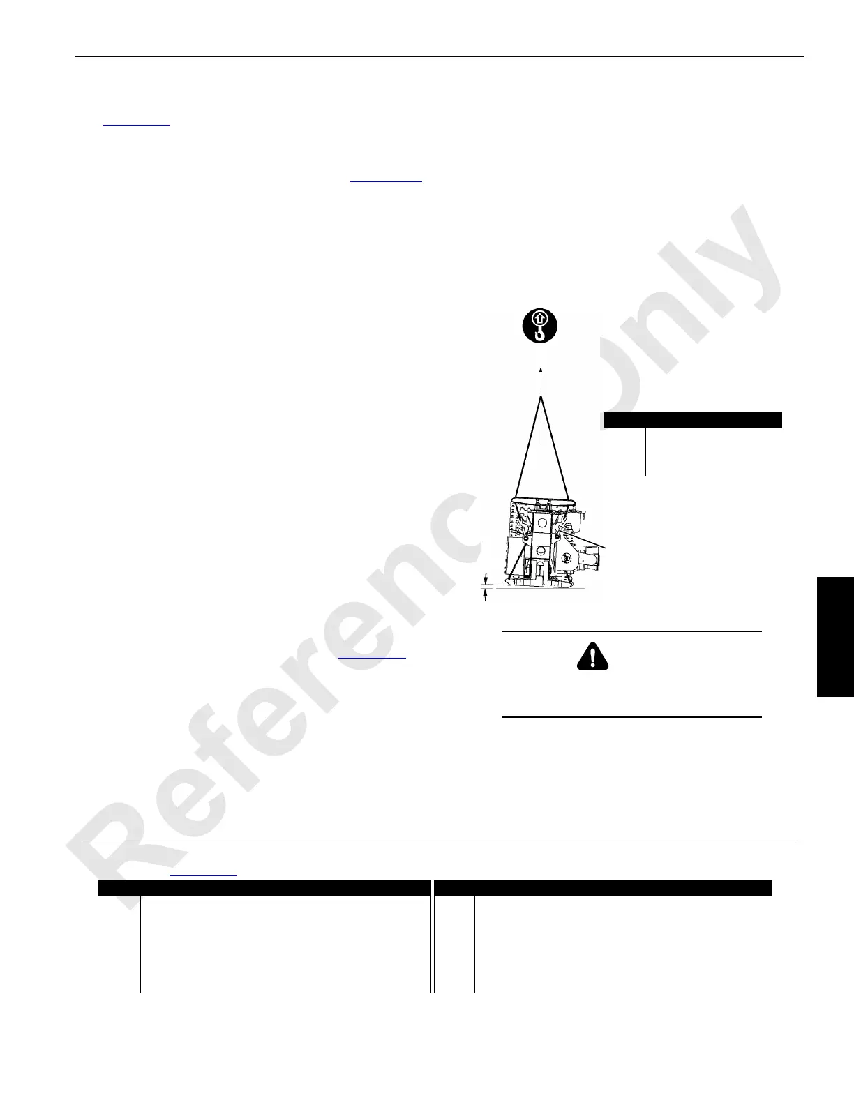
FIGURE 4-23
WARNING
Crush Hazard!
• Use proper size rigging to lift as shown.
Item Description
1 88,255 lb (40 032 kg)
2 3° for Installation
3 Shackle (4)
3
2
1
Legend for Figure 4-22 (quantities are for one crawler)
Item Description Item Description
1 Machined Surface 7 Chain Sling
2 Connecting Pin (2 places) 8 Crawler Assembly
3 Collar with Retaining Pin and Hair-Pin Cotter (2 places) 9 Lifting Lug with Shackle (4 places)
4 Right Crawler Pins Control 10 Crawler Hook (2 places)
5 Left Crawler Pins Control 11 Carbody Pin (2 places)
6 Assembly Block

 Loading...


