Manitowoc Published 12-05-17, Control # 032-23 3-21
18000 OPERATOR MANUAL OPERATING CONTROLS AND PROCEDURES
C – Indicators
See Figure 3-7 for the following indicators.
C1. RCL (Rated Capacity Indicator/Limiter) Controls
See RCL Manual for operation and calibration instructions.
C2. System Fault Alert
Glows RED and a beeper comes ON to alert operator that a
system fault exists (fault automatically appears on digital
display). See Digital Display Readings in this section for a list
of system faults, causes, responses, and corrective actions.
C3. Operating Limit Alert
Glows YELLOW and a buzzer comes ON to alert operator
that an operating limit has been reached (limit automatically
appears on digital display). See Digital Display Readings in
this section for a list of operating limits, function responses,
and corrective actions.
C4. Rear View Mirrors
Adjustable rear view mirrors on operator’s cab and rotating
bed allow operator to view rear of crane. Mirrors must be
rotated inward for shipping.
C5. Boom Angle Indicator
Shows angle of the boom in degrees above horizontal. The
boom angle can also be viewed on the digital display screen.
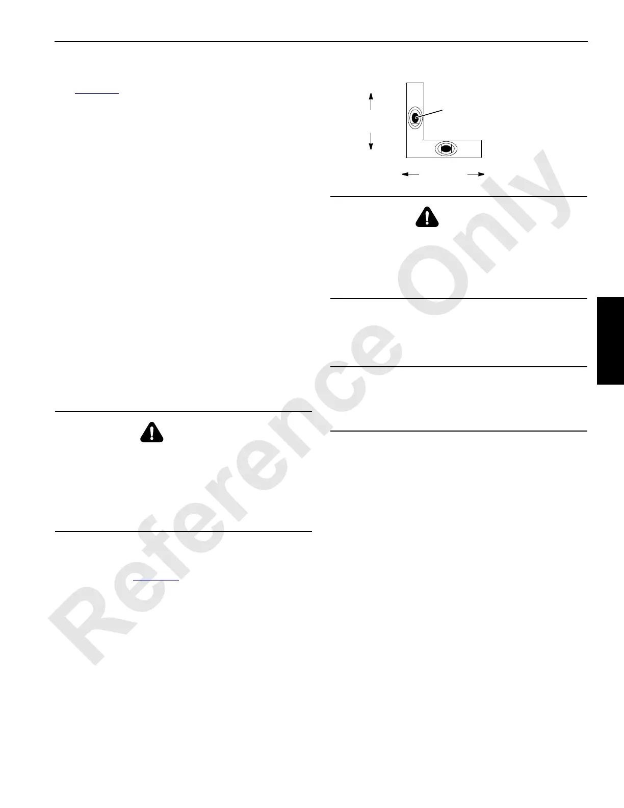
C6. Level
Indicates crane levelness from front to rear and from side to
side as shown in Figure 3-8
. The level is mounted on cab
support and is visible through right side window in operator’s
cab.
C7. Hydraulic Level and Temperature Gauge
Indicates hydraulic tank fluid level and temperature of oil in
hydraulic tank.
C8. Drum Rotation Indicators
Pin-type actuators are located under all drum handle covers.
They move UP and DOWN to signal operator, by feel, that
corresponding drum is turning. Indicator movement
corresponds to drum speed.
C9. Fuel Level
Indicates amount of fuel left in fuel tank.
C10. Engine Coolant Temperature
Indicates coolant temperature in engine cooling system. See
engine manual for operating specifications.
C11. Engine Oil Pressure
Indicates oil pressure in engine lubricating system. See
engine manual for operating specifications.
C12. Battery Voltage
Indicates condition of battery charging system.
WARNING
Overload Hazard!
In all cases, radius must govern capacity.
Use boom angle indicator only as a guide to position
boom near angle corresponding to radius for given load.
Exceeding radius given in capacity chart can result in
tipping or structural damage.
WARNING
Tipping Hazard!
Unless otherwise specified on capacity chart, all crane
operations must be performed with crane level to within
one percent of grade in all directions – 1 ft in 100 ft (0,3 m
in 30 m); otherwise, crane could tip.
CAUTION
Pump Damage!
Do not operate crane functions until hydraulic oil
temperature is at least 60°F (16°C).
FIGURE 3-8
Side-to-Side
Levelness
Front-to-Rear
Levelness
Centered bubble indicates level.
One half of bubble off center
indicates approximately one
percent of grade out of level.
3-113

 Loading...


