Manitowoc Published 12-05-17, Control # 032-23 4-95
18000 OPERATOR MANUAL SET-UP AND INSTALLATION
See Figure 4-46 for the remaining steps.
7. Using pin (17), attach pendant (16) to connecting link
(18) and to link (19) or pendant (21, View G) (also see
Figure 4-54
).
8. If used, pin pendant (23) to pendant (21).
9. Pin pendant (21 or 23) to links (12).
10. Repeat steps 1 - 8 on other side of insert.
When boom is raised, boom straps will lift intermediate
suspension into position and support inserts.
Install Standard Upper Boom Point
See Figure 4-47, View C for the following procedure.
Upper boom point cannot be installed if crane will be
equipped with a jib (fixed or luffing).
1. Using nylon lifting slings, lift upper boom point (26) into
position at lower boom point (25).
2. Remove pins (27) from connecting holes in upper boom
point.
3. Align upper connection holes (A) and install pin (27).
4. Rest upper boom point on ground.
5. Remove slings.
6. Install pin (27) in holes (B) as boom is raised.
Install Extended Upper Boom Point
See Extended Upper Boom Point Assembly Drawing at the
end of this section.
1. Remove lower boom point, as follows:
See Figure 4-49
for the following procedure.
a. Lower boom until sheaves in lower boom point (2)
are just clear of ground.
b. Attach hooks from assist crane to lifting holes (3) in
lower boom point (2).
c. Remove lower pins (4).
d. Hoist against lower boom point with assist crane
until upper pins (5) are loose and remove upper
pins.
e. Swing lower boom point away from boom top and
store.
f. Store pins (4 and 5) in lower boom point holes.
g. Lower boom top onto blocking at least 12 in (305
mm) high.
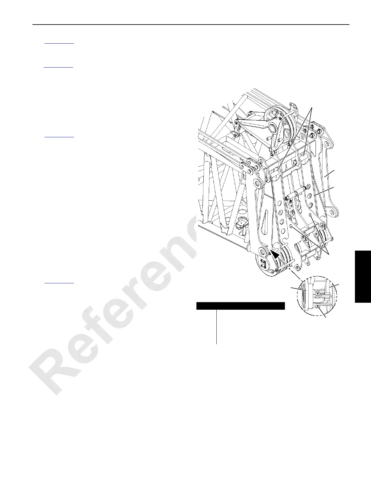
Item Description
1 Boom Top
2 Lower Boom Point
3 Lifting Holes
4 Lower Pin with Cotter Pins
5 Upper Pin with Cotter Pins
5
1
2
2
1
4
3
FIGURE 4-49
4-186

 Loading...


