Manitowoc Published 12-05-17, Control # 032-23 4-123
18000 OPERATOR MANUAL SET-UP AND INSTALLATION
RIGGING WINCH OPERATION
If your crane is equipped with the optional rigging winch
(Drum 7), see the Rigging Winch Assembly drawing at the
end of this section for wire rope routing.
Selecting Rigging Winch Mode
NOTE See Section 3 in this manual for operation of the
crane mode selector.
TO TURN RIGGING WINCH MODE ON —
1. Press bottom of confirm/select switch until RIG WINCH
appears in display.
2. Press top of confirm/select switch to CONFIRM Rig
WINCH mode.
*W will appear next to main mode as shown in
Figure 4-69
. The boom hoist handle on left console will
now operate the rigging winch.
TO TURN RIGGING WINCH MODE OFF —
1. Turn confirm/select key switch to SELECT position until
RIG WINCH appears in display.
2. Turn confirm/select key switch to CONFIRM position. *W
will disappear from display indicating rigging winch
mode is OFF.
The rigging mode will automatically turn OFF when
power to the control system is turned off.
Operating Rigging Winch (Past Production)
1. Select and confirm rigging winch mode.
2. Pay out rigging rope either by pushing boom hoist
handle forward or by turning on winch free-spool feature,
as follows:
a. Pull locking pin (2, Figure 4-70
) out and hold.
b. Pull knob (3) out.
c. Release locking pin (2).
d. Rope can now be pulled off winch drum manually.
3. Route rigging rope through guide sheaves in boom butt.
See Rigging Winch Assembly drawing at the end of this
section.
4. Route rigging rope through load block and boom point
sheaves, through guide sheaves on boom, and connect
rigging rope to end of rope on desired drum (1, 2, 3, or
6). See Rigging Winch Assembly drawing at the end of
this section.
5. If on, turn off winch free-spool feature:
a. Pull locking pin (2, Figure 4-70
) out and hold.
b. Push knob (3) in.
c. Release locking pin (2).
6. Remove slack from rigging rope (pull boom hoist handle
back) prior to paying out rope from drum.
NOTE The stall line pull of the rigging winch is regulated
with a proportional relief valve controlled by the
crane’s programmable controller.
If engine speed is set too low when attempting to
haul in rigging rope, the rope may go slack. If this
happens, slowly increase engine speed until the
rope tightens.
FIGURE 4-69
Crane Mode – STANDARD ON *W
Main
Mode
Rigging Winch ON
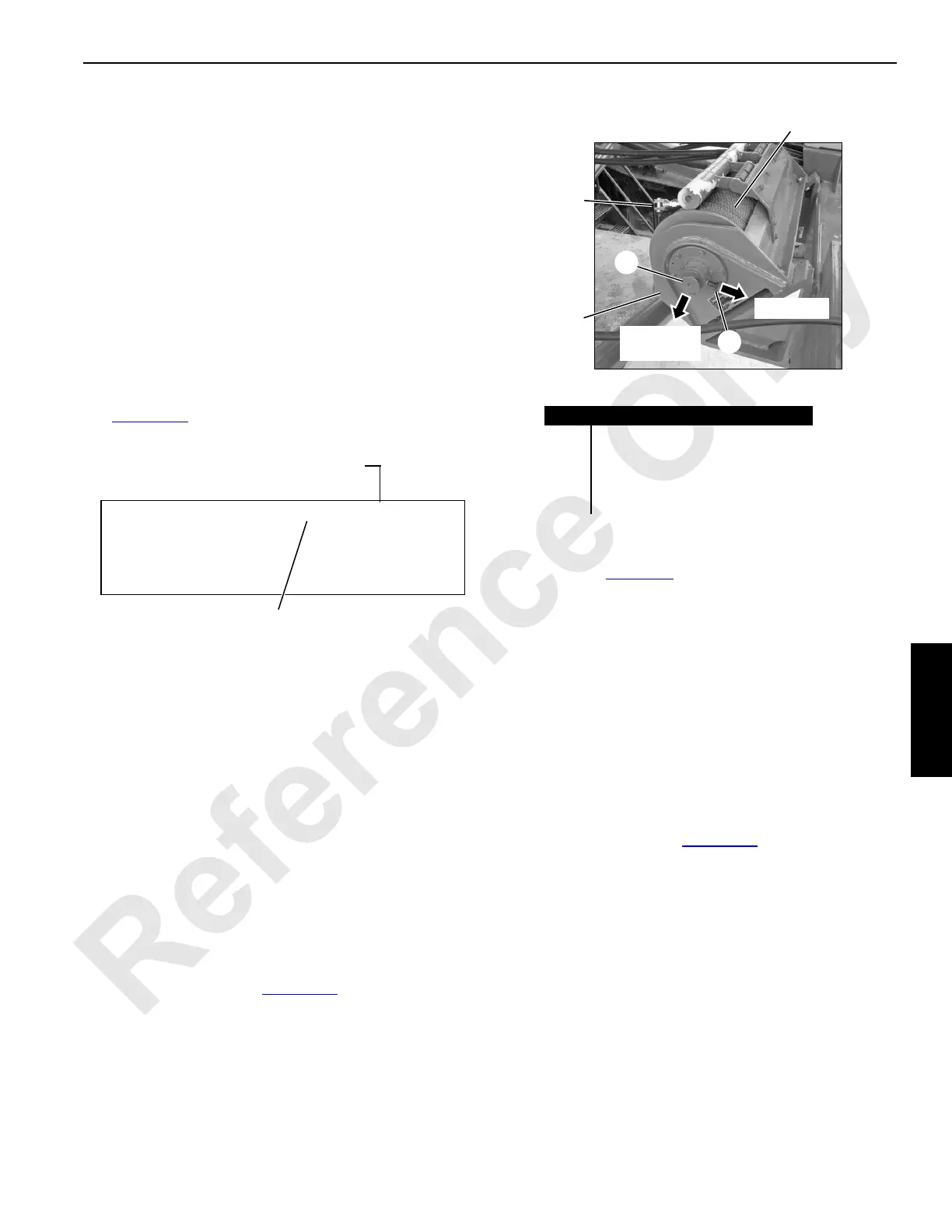
FIGURE 4-70
Item Description
1 Rigging Winch (Drum 7)
2 Locking Pin
3Knob
4 Rope End Connector (see NOTE)
5 Wire Rope: 5/16 in (8 mm) Diameter
P2314a
4
1
5
NOTE Rope end connector can be
connected to pad eye on end of
rope from drum as shown in
Figure 4-68
.

 Loading...


