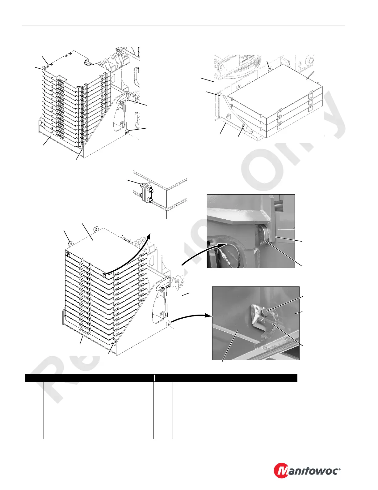
FIGURE 4-25
Item Description Item Description
1 Lifting Lug (4 places each tray and box) 9 Hook
2 Carbody Tray 10 Fixed Pin – Rotating Bed (2 places each side)
3 Carbody 11 Notched Pin – Rotating Bed (2 places each side)
4 Hooked Connector (not visible) 12 Retaining Pin with Snap Pins
5 Carbody Box (3 each end) 13 Fabricated Upperworks Box
6 Lifting Lug (4 each tray and box) 14 Links (stored for Luffing Jib only)
7 Upperworks Tray (1 each side) 15 Cast Counterweight Upperworks Box
8 Rotating Bed 16 Cast in Lug
View B
10
View C
7
8
11
12
9
P1968
P1967
Maximum Counterweight Arrangement Shown
See Counterweight Assembly Drawings at End
of this Section for Optional Arrangements
View A
5
2
1
4
3
1
View D
Fabricated Counterweight
(2 places)
13
7
6
8
6
View E
(4 places Luffing Jib Prepared Only)
14
4-129
4-130
4-131

 Loading...


