SET-UP AND INSTALLATION 18000 OPERATOR MANUAL
4-88
Published 12-05-17, Control # 032-23
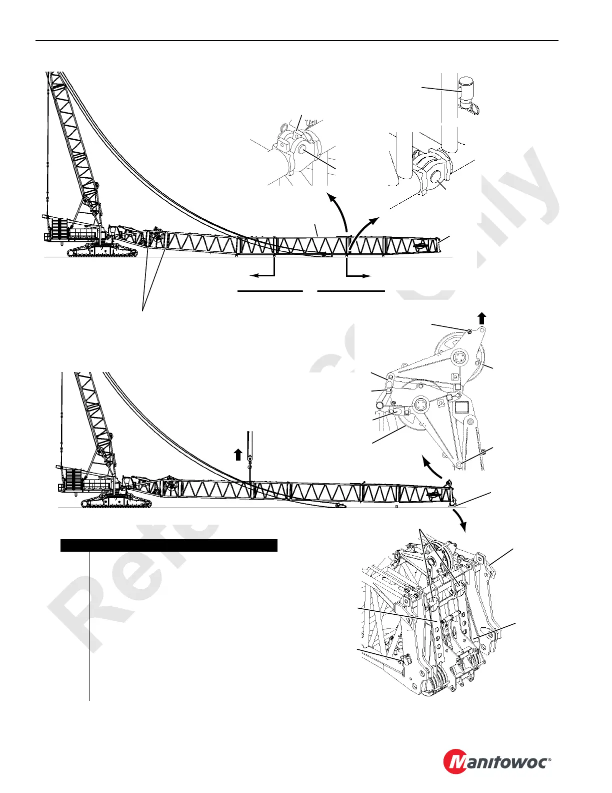
#55 Boom
#79A Boom (if equipped)
5
View A
From Assist
Crane
View E
4-174
(operating)
Operating
Hole
View D
6
Storage
Hole
Lift Here
6
7b
7a
7c
4-175
Blocking
1a
Item Description
1a 40 ft (12,2 m) #79A Transition Insert (if required)
1b Boom Inserts
2 Fixed Horizontal Pin
3 Hooked Connector
4 Bottom Connecting Pin with Safety Pin
5 30 ft (9,1 m) Boom Top
6 Wire Rope Guide
7a Pin with Snap Pins (two places)
7b Link and Pins and Snap Pins (two places)
7c Link and Pins and Snap Pins (stored)
8 Pin with Cotter Pins
9 Pin with Cotter Pins (stored)
10 Lower Boom Point Assembly
see Boom Rigging Assembly Drawing
1b
NOTE If equipped with grease lines for Drum 6
guide sheave in 40 ft (12,2 m) insert,
connect grease lines to couplers at these
locations.