GROVE 6-3
CD3340B/YB4411 ENGINE AND ENGINE SYSTEMS
Published 04/07/2015 Control # 569-00
gasket. These holes are orifices and their size is
critical. Do not enlarge the size of the orifices. To do
so will disturb the coolant flow and will not solve
any overheating problem. If you use water without
a corrosion inhibitor for even a short period, the cup
plugs will rust through, allowing coolant leakage.
An incorrect or malfunctioning radiator cap can
result in the loss of coolant and engine running hot.
Any sudden loss of coolant from a heavily loaded
engine can result in severe damage to the pistons
and cylinder bore.
NOTE: Some corrosion inhibitor mixtures contain soluble
oil which can have an adverse effect on some
types of water hoses.
Thermostat
A malfunctioning thermostat can result in the engine running
hot or cold. If it becomes necessary to replace the thermostat
refer to the engine manual furnished with the crane.
ENGINE ELECTRICAL SYSTEM
The engine electrical system, the charging and starting
circuits, as well as the sending units, are described in
SECTION 3.
ENGINE FUEL SYSTEM
Diesel Engine Fuel System Description
The diesel engine fuel system (Figure 6-1) includes a fuel
tank, a fuel level sender and gauge, a fuel filter, a fuel pump,
fuel lines from the tank to the fuel pump to the fuel filter, fuel
lines from the fuel filter to the fuel injector pump to and from
the fuel injectors back to the fuel tank.
A fuel supply line carries fuel from the bottom of the fuel tank
to the engine fuel pump. A line carries the fuel from the
engine fuel filter to the engine fuel pump. Fuel that has been
filtered flows to the fuel injector pump.
Fuel is distributed to the fuel injectors from the fuel injector
pump. Excess fuel from the fuel injector pump is returned to
tank.
Fuel Tank
The fuel tank is located on the right side of the crane. It is a
welded box construction with a suction tube installed in the
fuel support port. The tube inhibits sediment and water from
being picked up off the bottom and sent to the engine.
Fuel Level Sender and Gauge
The fuel level sender and gauge are described in the Section
3, Electrical System.
Fuel Pump
The fuel pump is installed on the engine and is used to pump
fuel from the fuel tank and send it under pressure to the fuel
filter and injection pump.
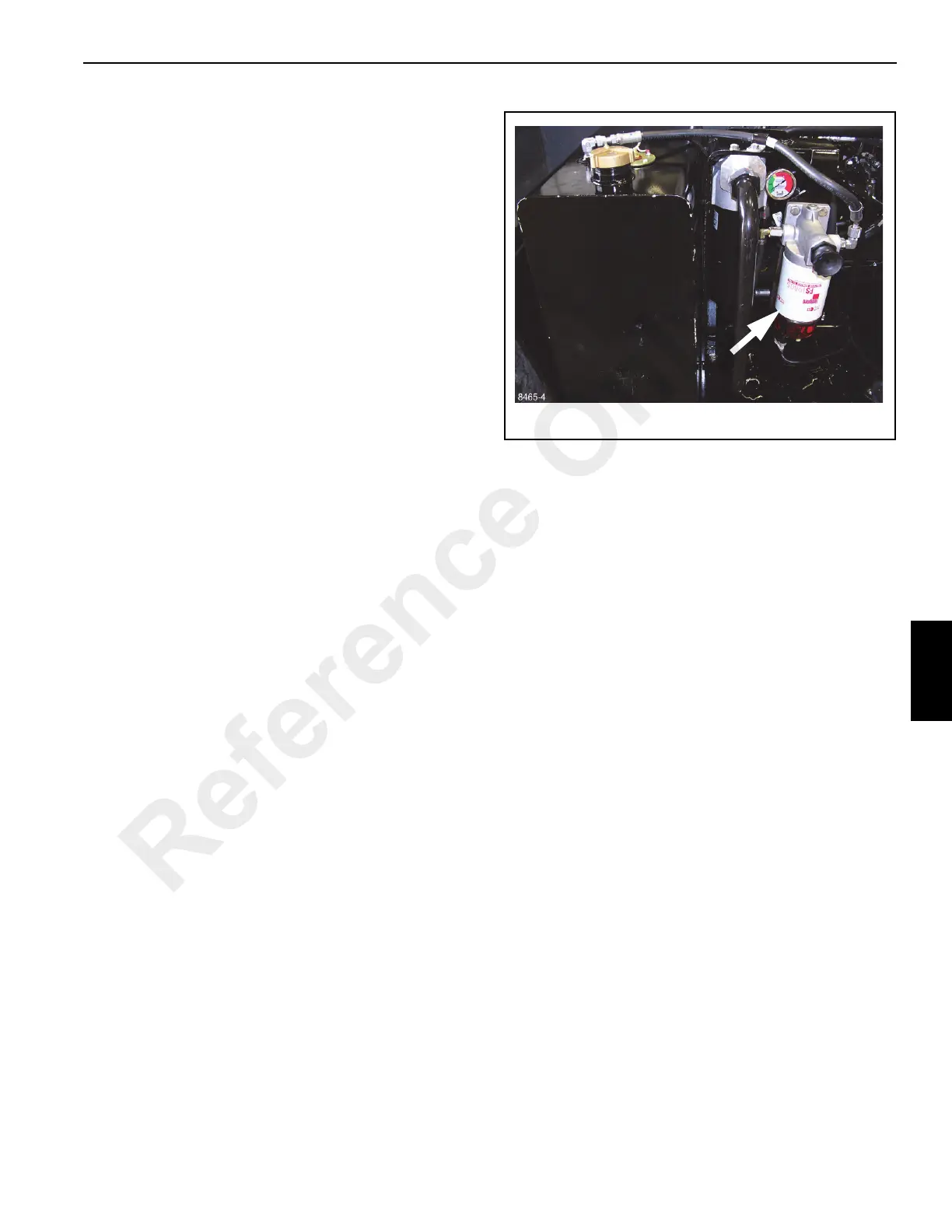
Fuel Filter
The filter (Figure 6-1) is used to collect contaminants and
water that has accumulated in the fuel and is not picked up
by the in-line filter. It must be serviced at regular intervals.
See Section 5, Preventive Maintenance for maintenance
intervals.
The fuel filter includes a priming button. This button is used
to bleed the fuel system if one of the following should occur:
• The fuel filter is not filled prior to installation.
• The injection pump is replaced.
• High pressure fuel line connections are loosened or
lines are replaced.
• Initial start up or start up after an extended period of
time.
• The fuel tank has run empty.
Refer to the diesel operator’s manual furnished with this
crane for bleeding procedures.
Fuel Injection Pump
The fuel injection pump is a distributor-type pump with a
mechanical flywheel-type governor. The pump is flange
mounted and is driven from the engine timing case.
Reference Only

 Loading...


