GROVE 8-39
CD3340B/YB4411 AXLES/DRIVE SHAFTS/WHEELS AND TIRES
Published 04/07/2015 Control # 569-00
5. Repeat steps 1 through 3 and install a flange yoke (1) to
each end of the drive shaft.
6. Apply SAE 140 oil to the splines on the slip tube (3).
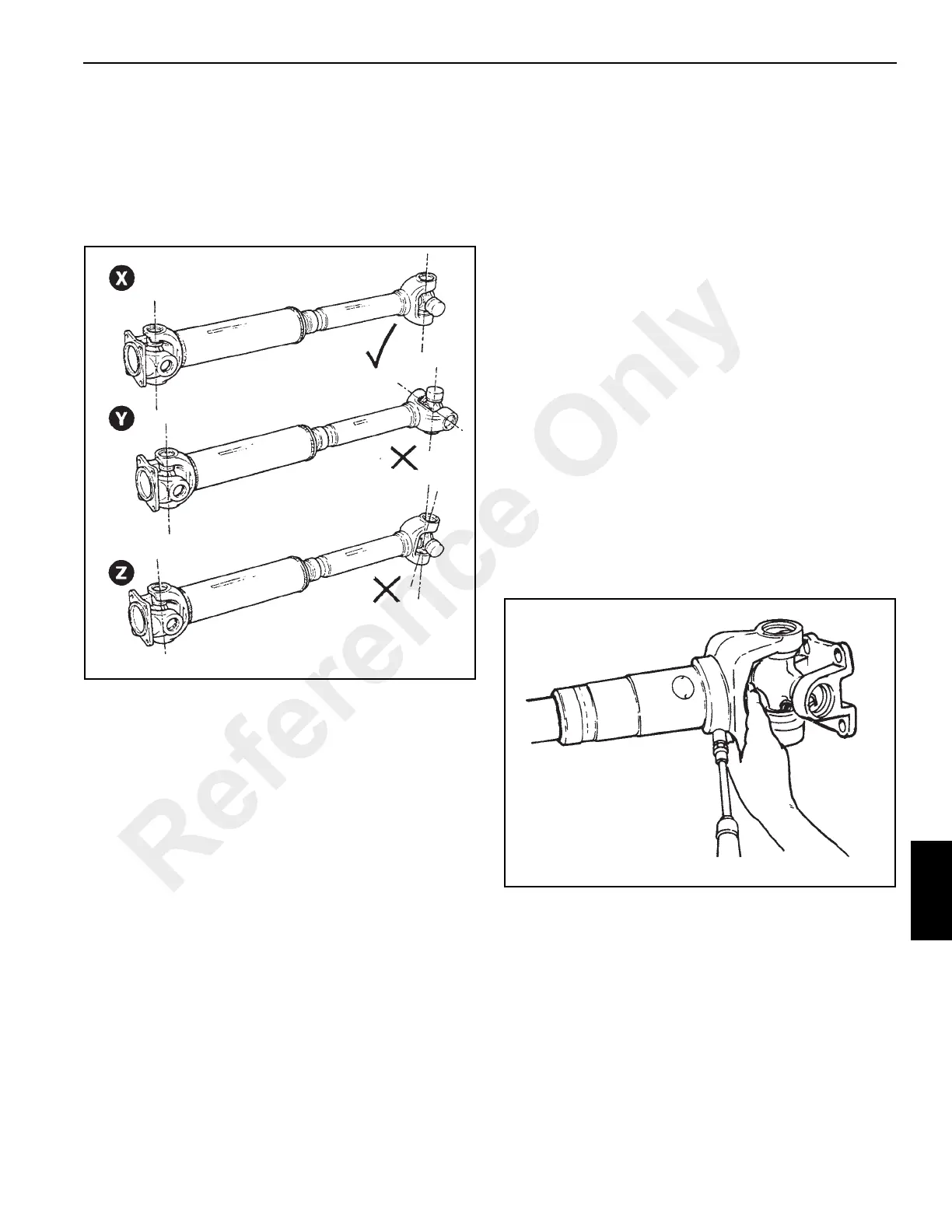
Assemble the dust cap assembly to the slip tube. Slide
the slip tube into the slip yoke (4). Make sure both ends
of the drive shaft are in the same plane. See “X” in
Figure 8-141. Tighten the dust cap assembly.
Installation
1. Fasten the flange yoke to the parking brake disc on the
front axle with four capscrews and lockwashers.
NOTE: The drive shaft must have both ends exactly on the
same as shown in “X” of Figure 8-141. The yokes
must not be at right angles as at “Y” or at an
intermediate angle as in “Z”.
2. Fasten the other end to the transmission with four
capscrews and self-locking nuts.
3. Apply a Lithium Base, E.P. No. 2 bearing grease to the
three grease fittings on the drive shaft. One fitting on
each journal cross and one on the slip yoke. Apply the
grease until it exits through the seals. See Lubrication
Procedure on page 8-39.
4. Check the drive shaft for correct balance before the
machine is put into operation. Lower the outriggers to lift
the wheels off the ground. Operate the drive train and
check for vibration. If vibration is found, stop the engine
and check the drive shaft. Make sure the drive shaft
yokes are in the same plane. If they are the drive shaft
needs to be balanced. Do not drive the crane with an
unbalance drive shaft, possible damage to drive train
could occur.
Lubrication Procedure
The drive shaft is an important part of the drive train and
needs regular maintenance. There is a grease fitting on the
slip joint and on each journal bearing cross. Apply grease to
these fittings after every 50 hours of operation. Use a Lithium
Base, E.P. No. 2 bearing grease. Always apply enough
grease to remove the old grease. On the slip joint, apply
grease to the grease fitting until grease comes through the
hole in the end of the shaft. Put your finger over the hole
(Figure 8-142) and continue to apply grease until the grease
shows at the seal on the slip joint.
Reference Only

 Loading...


