HYDRAULIC SYSTEM CD3340B/YB4411
4-12
Published 04/07/2015 Control # 569-00
HYDRAULIC SWIVEL
General
The hydraulic swivel is at the center of rotation of the mast.
The purpose of the hydraulic swivel is to permit the flow of oil
between the hydraulic components on mast and boom and
the components on the lower structure during any rotation of
the mast.
The hydraulic swivel has seven passages (Figure 4-3).
Grooves and ports in the shaft align with ports in the housing.
Seals between the grooves of the shaft prevent leakage
between the passages. The seals fit tightly against the
housing. The housing rotates with the mast and the shaft is
stationary.
Functions
The numbers of each port is stamped on the housing and on
the lower end of the shaft.
Port No. 1
Hydraulic oil under pressure flows through this port when the
hoist block is being raised. When lowering the hoist block the
hydraulic oil under low pressure flows through this port.
Port No. 2
Hydraulic oil under pressure flows through this port when the
hoist block is being lowered. When raising the hoist block the
hydraulic oil under low pressure flows through this port.
Port No. 3
Hydraulic oil under pressure flows through this port when the
boom is being lowered. When raising the boom the hydraulic
oil under low pressure flows through this port.
Port No. 4
Hydraulic oil under pressure flows through this port when the
boom is being raised. When lowering the boom the hydraulic
oil under low pressure flows through this port.
Port No. 5
Hydraulic oil under pressure flows through this port when the
boom is being retracted. When extending the boom the
hydraulic oil under low pressure flows through this port.
Port No. 6
Hydraulic oil under pressure flows through this port when the
boom is being extended. When retracting the boom the
hydraulic oil under low pressure flows through this port.
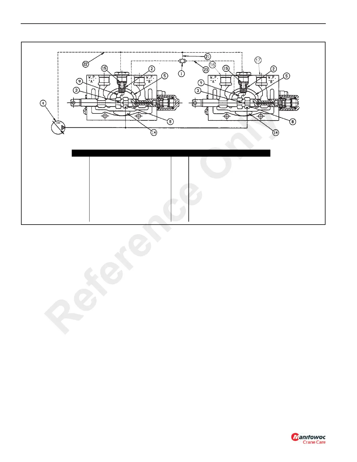
FIGURE 4-2
Item Description Item Description
1 Load Sense Shuttle 14 Return Core (To Tank/Outlet)
2 Compensator 15 Bias Spring
3 Spool 16 Work Port A
4 Pump 17 Work Port B
5 Work Port Feeder Core (Bridge) 21 Section Load Sense Line
8 Pump Supply (From Inlet Port) 22 Load Sense & Compensator Signal
Line
9 Pump Supply After Spool to
Compensator
23 Load Sense Shuttle Signal Line
From Work Port Feeder Core
(Bridge)
a0725
Reference Only