GROVE 7-3
CD3340B/YB4411 TRANSMISSION AND TORQUE CONVERTER
Published 04/07/2015 Control # 569-00
DESCRIPTION OF OPERATION
Torque Converter
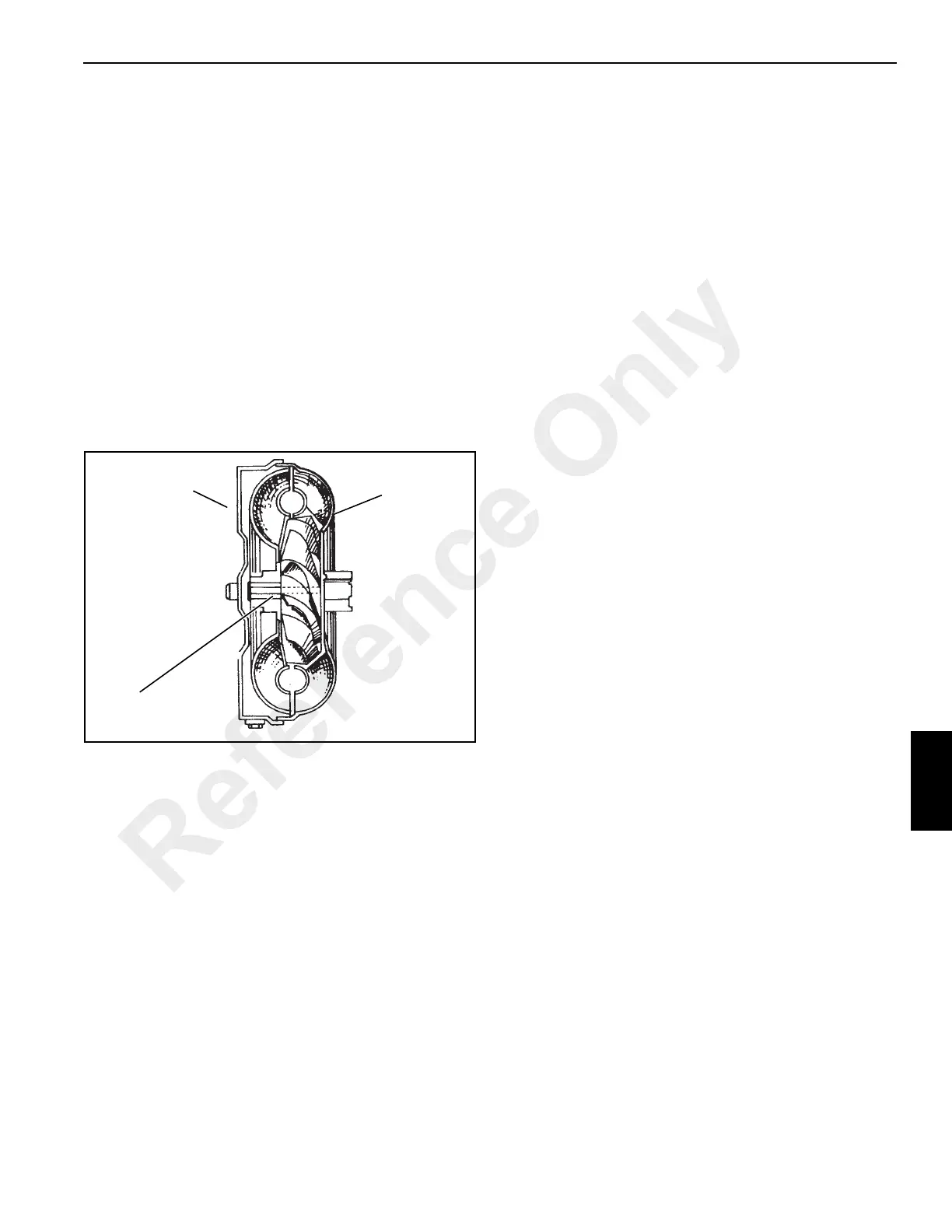
The torque converter (Figure 7-1) is the hydraulic link
between the engine and the drive train. There are three main
components in the torque converter:
• A turbine
• An impeller (pump)
• A stator and One-Way Clutch
The impeller is the pump for the torque converter. This
component starts the movement of the oil to the other
components. The impeller is connected to the engine
flywheel through the torque converter and a drive plate. The
impeller rotates at engine speed. Similar to a centrifugal
pump, the impeller takes oil at the inner diameter and
releases the oil at the outer diameter.
Cross Section of Torque Converter
The turbine is opposite the impeller and is connected by
splines to the input shaft of the Powershift Transmission. The
turbine receives oil at the outer diameter and releases the oil
to the stator at the inner diameter. The movement of oil from
the impeller to the turbine makes a multiplication of torque
possible. The torque converter gives maximum torque when
the turbine is at zero (0) rpm.
The stator is between and at the center of the impeller and
turbine. The stator changes the direction of the oil which
leaves the turbine so the oil will enter correctly again into the
impeller.
The torque converter and transmission have a common
hydraulic system. Figure 7-1 shows the arrangement of the
system.
NOTE: Normal operating temperature is 82° - 88°C (180° -
190°F). High temperatures will cause damage and
leakage in the seals and gaskets of the torque
converter. Do not continue operation if the
temperature increases above 82° - 88°C (180° -
190°F). A warning light on the cab instrument panel
will illuminate when the temperature rises above a
safe temperature. Put the transmission in neutral
position and let the engine run at low RPM until the
temperature returns to normal and the warning light
goes out. If temperature does not return to normal,
check for restriction in the lubrication and cooling
lines of the torque converter.
Transmission
The Powershift Transmission (Figure 7-2) is an electo-
hydraulic transmission unit. Gear shifting and direction
selection are controlled using multi-disc clutch packs.
Electrically operated solenoid valves divert pressurized oil
(provided by pump (Q, Figure 7-2) to the selected clutch
packs.
A combined lever/swivel switch (travel select lever) on the
steering column actuates both gear ratio and direction
solenoids.
The Powershift transmission consists of a torque converter A
(Figure 7-2), input clutch assembly B, forward clutch C,
layshaft assembly E, main shaft assembly D, and a parking
brake disc J mounted on spline output shaft K.
The torque converter is a fluid coupling bolted to a drive plate
which is bolted to the engine flywheel. As the engine
crankshaft begins to rotate, the torque converter gives a
smooth power takeoff gradually increasing the torque
transmitted. This torque is transferred from the torque
converter assembly to the clutch/gear assemblies via the
input shaft H.
The input clutch assembly B contains two hydraulically
operated clutches; one clutch provides reverse low ratio
drive and other a reverse high ratio drive. The three-position
solenoid G, when energized, directs pressurized oil to either
the reverse low or reverse high clutch.
The forward clutch assembly C is similar to the input clutch
assembly. It contains two hydraulically operated clutches;
one clutch provides forward low ratio drive and the other
forward high ratio drive. The three-position solenoid valve L,
when energized, directs pressurized oil either to the forward
low or forward high clutch.
Forward drive is transmitted via constant meshing of spur
gears Z.
Both the mainshaft and the layshaft assemblies have a
single clutch each. The three-position solenoid M, when
energized, directs pressurized oil to either the mainshaft
clutch or the layshaft clutch.
A0230
FIGURE 7-1
Turbine
Input
Stator
Impeller
Output
Reference Only

 Loading...


