Grove Published 3-25-2020, Control # 595-10 4-21
GRT8100 OPERATOR MANUAL SET-UP AND INSTALLATION
BI-FOLD SWINGAWAY, OFF-SETTABLE
BOOM EXTENSION
NOTE: Manual and hydraulic off-settable boom extensions
install and remove the same way.
Description
A 10 m to 17 m (33 ft to 56 ft) bi-fold swingaway, manual or
hydraulic off-settable boom extension provides additional
boom reach. The boom extension weighs approximately
1,102 kg (2,430 lb).
The boom extension is stowed on the right side of the boom
base and is easily attached or removed from the boom nose
using a remotely operated electric extension support and two
stowage pins.
Throughout the following instructions the lattice section
portion of the boom extension is referred to as the boom
extension base section and the solid steel boxed section
portion is referred to as the boom extension fly section.
Boom Extension Rigging Mode
This crane is equipped with a boom control system that
enters a Boom Extension Rigging Mode when a minimum
boom length is detected. The crane will not allow the
following movements while in the Boom Extension Rigging
Mode:
• Extension of boom in Auto Mode with A Mode selected.
• Extension of boom in Manual Mode, with Boom
Section 2-4 selected.
The Boom Extension Rigging Mode requires the boom to be
extended, in Auto Mode with B Mode selected or Manual
Mode with Section 1 selected, until the boom automatically
stops and is clear of the stowage ramps and stowage pins on
the front stowage bracket.
To exit the Boom Extension Rigging Mode, the boom must
be fully retracted, causing sections 1 and 2 proximity
switches to activate. Boom operating mode restrictions are
removed after exiting the Boom Extension Rigging Mode.
Erecting Boom Extension
Refer to Figure 4-20.
1. Fully extend and set outriggers.
2. Position boom over front of crane.
3. Set boom manual/automatic mode selector switch to
AUTO position.
4. Set boom A/B mode selector switch to B mode.
5. Fully retract all boom sections.
6. Lower boom to minimum elevation.
7. Lower front outriggers until front wheels are on ground.
NOTE: Auxiliary boom nose (rooster sheave) does not
have to be removed. If reeved, remove hoist cable
from sheave.
8. Rig main hoist or optional auxiliary hoist cable for single
part line with only wedge socket on cable end.
9. Attach rope to tip of boom extension base section to help
swing it around to the front of the boom nose.
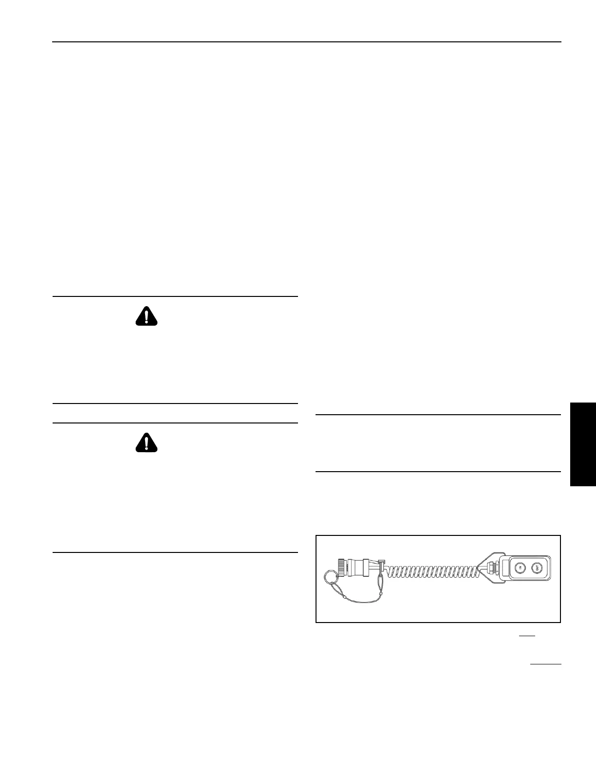
10. Remove caps and connect boom extension mount
control pendant to connector on front of boom base.
NOTE: If erecting boom extension base section with
boom
extension fly section, skip to step 13.
If erecting boom extension base section without
boom extension fly section, perform steps 11
and 12.
DANGER
Before attempting to erect or stow the boom extension,
read and follow all safety decals installed on the boom,
boom nose, boom extension, and stowage brackets.
Lifting over the boom extension base section is strictly
prohibited when the boom extension fly section is erected
or folded along side of the boom extension base section.
DANGER
Extending boom sections 2 through 4 during erection or
stowage of the boom extension can cause
disengagement of the anti-roll guides and allow
uncontrolled movement of the boom extension, resulting
in death, personal injury, or property damage.
Always ensure crane is in B mode during erection or
stowage of the boom extension. Never erect or stow the
boom extension in recovery mode.
CAUTION
If boom extension fly section is not to be erected,
disconnect it from boom extension base section and keep
attached to boom stowage brackets on boom base.

 Loading...


