SET-UP AND INSTALLATION GRT8100 OPERATOR MANUAL
4-36 Published 3-25-2020, Control # 595-10
REMOVABLE COUNTERWEIGHT
Counterweight and optional attached slab are installed and
removed using hydraulic cylinders controlled by a
counterweight control panel located on each side of the
superstructure. The counterweight assembly is held in place
by a hydraulic cylinder and locking pins with pin clips.
Counterweight and slab are lowered or lifted from two
centering pins located on the rear deck.
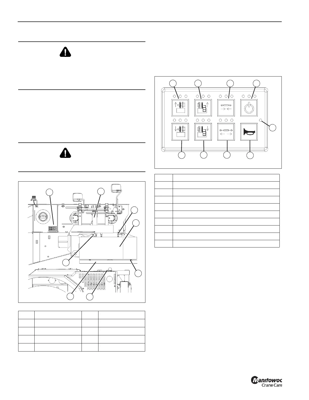
Counterweight Control Panel
Counterweight control panels are located on each side of the
superstructure between the boom pivot and main hoist. Only
one control panel can be used at a time. The crane engine
must be running with parking brake ON and no other
functions enabled for system to be fully operational.
Flashing green LED (1) indicates main power is on. Enable
and Horn buttons are illuminated and active.
Three LED’s above each button indicate:
Green - Function enabled.
Yellow - Error condition.
Red - Function not available or system not enabled.
NOTE: The horn button (3) is always active. Enable does
not have to be pressed before using the horn.
The Enable button (2) must be pressed and released before
selecting a function. The function must be selected within
five seconds after pressing the Enable button or the system
will time out and the Enable button must be pressed again.
If the Enable button is pressed and held for more than
2 seconds, the red LED will illuminate. No other functions are
available until the button is released and pressed again.
DANGER
Falling counterweight can crush and cause death or
serious injury.
Ensure all mounting pins are properly installed and
locked, during and after operating the counterweight
removal system.
DANGER
Travel is not permitted with removable counterweight on
carrier deck.
Item Description Item Description
1 Control Panel 5 Leveling Bolts
2 Lift Cylinder 6 Centering Pins
3 Leveling Bolt (4 ea) 7 Optional Slab
4 Counterweight 8 Lock Cylinder
FIGURE 4-25
1
2
4
5
6
8
8658-1
3
7
Item Description
1 Main Power Indicator
2 Keypad Enable
3Horn
4 Lock Cylinder Retract
5 Lock Cylinder Extend
6 Left Counterweight Cylinder Lower
7 Right Counterweight Cylinder Lower
8 Left Counterweight Cylinder Raise
9 Right Counterweight Cylinder Raise
FIGURE 4-26
8658-2
1
9
8
2
4
7
6
5
3

 Loading...


