SET-UP AND INSTALLATION GRT8100 OPERATOR MANUAL
4-24 Published 3-25-2020, Control # 595-10
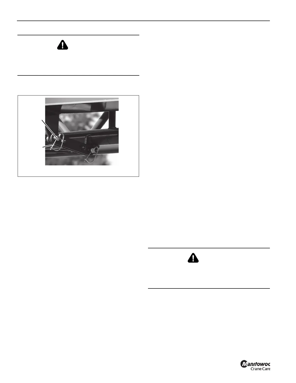
4. Remove retainer clip (2, Figure 4-15) and remove
pin (1).
5. Slightly raise or lower boom to help control boom
extension fly section swing. Using rope attached to tip of
boom extension fly section, swing it in front of the boom
extension base section until boom extension fly section
attachment fittings engage with the left side boom
extension base section anchor fittings.
6. Install attachment pin into left anchor and attachment
fittings of the boom extension base section and boom
extension fly section. Secure attachment pin with
retaining clip.
7. Lower boom and remove rope from tip of the boom
extension fly section.
Stowing Boom Extension
NOTE: Boom extension must be set at 0° offset. If boom
extension is manually off-settable, refer to Setting
Boom Extension Manual Offset, page 4-27.
Refer to Figure 4-20.
1. Fully extend and set outriggers.
2. Position boom over front of crane.
3. Fully retract all boom sections.
4. Set offset to 0° if not already done so. Refer to the
applicable procedures in this section.
5. Lower boom to minimum elevation.
6. Lower front outriggers until front wheels are on ground.
7. Set boom manual/automatic mode selector switch to the
AUTO position.
8. Set boom A/B mode selector switch to the B mode.
9. If the boom extension fly section is erected, remove the
clip pins and cable retaining pins at the boom extension
fly section sheave, then remove the hoist cable.
Reinstall cable retaining pins and secure with clip pins.
If only the boom extension base section is erected,
remove the clip pins and cable retaining pins at the
boom extension base section sheave, then remove the
hoist cable. Reinstall cable retaining pins and secure
with clip pins.
Remove the clip pin and cable retaining pin at the mast
sheave (6, Figure 4-20), then remove the hoist cable.
Reinstall cable retaining pins and secure with clip pins.
10. Stow mast assembly:
a. Remove pin from the upright position lug of the mast
assembly.
b. Lower the mast assembly and install the pin in the
stowed position lug.
c. Secure with clip pin.
11. Disconnect hydraulic lines (if required) Refer to
Connecting and Disconnecting Boom Extension,
page 4-32.
12. Disconnect the anti-two block cable(s). Refer to
Connecting and Disconnecting Boom Extension,
page 4-32.
13. If erected, stow boom extension fly section as follows:
a. Attach rope to the boom extension fly section tip.
b. Raise the boom to horizontal.
c. Remove left attachment pin connecting the boom
extension fly section to the boom extension base
section. Stow attachment pin in the stowage holder
on the boom extension base section and secure
with retaining clip.
d. Slightly raise or lower boom to help control the
boom extension fly section swing. Using rope
attached to tip of boom extension fly section, swing
DANGER
When erecting the boom extension fly section, ensure all
personnel and equipment are kept clear of swing path.
Uncontrolled movement of the boom extension fly section
can cause death, injuries, or damage to equipment.
DANGER
When stowing the boom extension fly section, ensure all
personnel and equipment are kept clear of the swing path.
Uncontrolled movement of boom extension fly section can
cause death, injuries, or damage to equipment.

 Loading...


