Grove Published 4-09-2021, Control # 364-11 3-41
RT765E-2 OPERATOR MANUAL OPERATING CONTROLS AND PROCEDURES
An Anti-Two Block Device is also incorporated into the
system to prevent the hook block or overhaul ball from
coming into contact with the boom nose or boom extension.
This condition will cause a lockout of hoist up, boom down,
and telescope out, and also provide a visual and an audible
alarm.
Refer to the RCL Operator Handbook for more detailed
information on the function of the RCL system.
Using the Tare Function
The tare function is not shown on the RCL Display Module
(RDM) at crane startup.
To show the tare function, do one of the following:
• Press the Screen Toggle Button (1, Figure 3-20) at the
Jog Dial to select the RDM screen control.
From the RCL Setup Screen, press the Tab Button (2).
- or -
• Press the Tab Button (3, Figure 3-20) on the RDM
Navigation Control Pad.
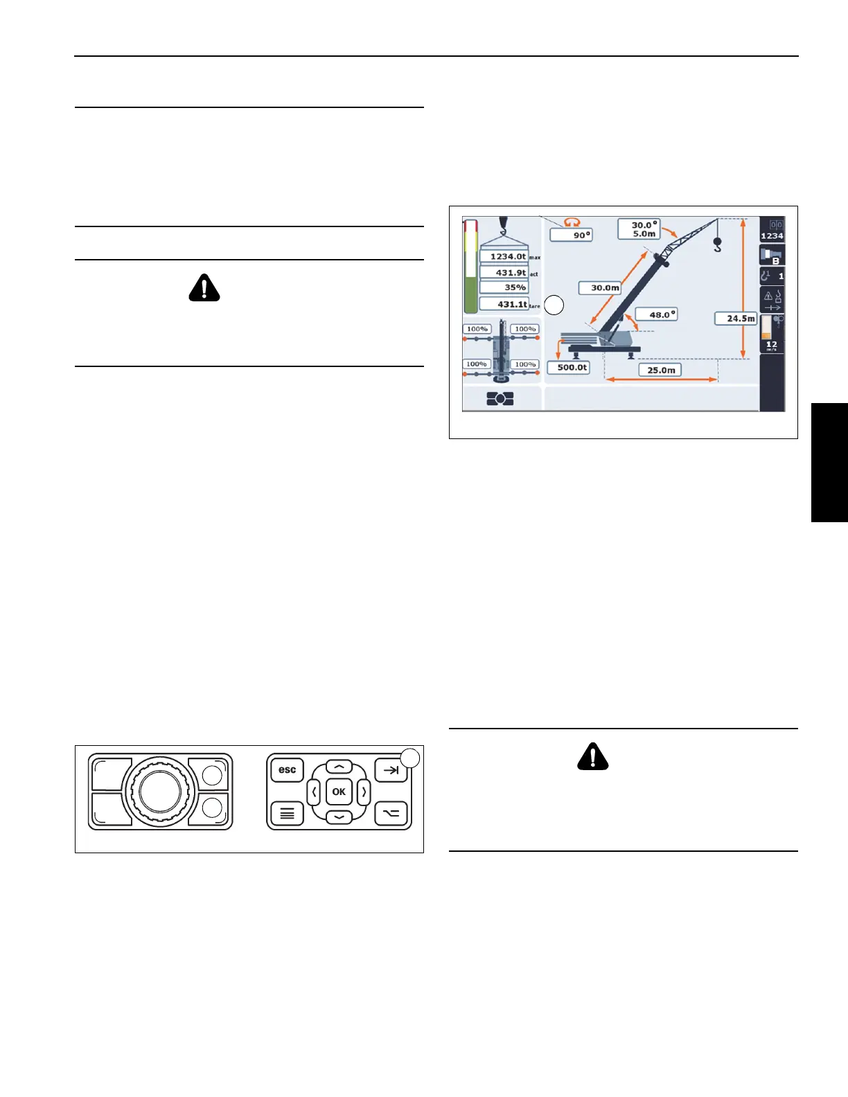
The tare weight (1. Figure 3-21) is shown below the
percentage of the actual versus maximum percent load. The
tare weight value equals the actual weight value until the tare
weight is zeroed out. The operator sets the tare weight to
zero by pressing the Tab Button on either the Jog Dial or the
RDM Navigation Control Pad.
If the Operator changes the Load Chart Code Number, the
tare weight will be reset to equal the current Actual Weight.
To disable the tare function, the operator must switch power
off and back on using the Ignition Key Switch.
NOTE: The tare function does not change nor override the
value of the Actual Load, and does not affect the
Rated Capacity Limiter (RCL) and its function
lockouts.
Control Lever Lockout System
The control lever lockout system consists of hydraulic
solenoid valves (located in the directional control valves)
which are in series between the hydraulic remote control
valves in the cab and the pilot-operated directional control
valves. When the valves are actuated, they prevent pilot flow
between the hydraulic remote control valve in the cab and
the appropriate directional control valve. The valves are
activated in such a manner as to prevent worsening the
condition, i.e. boom down, telescope out, or hoist up. The
control lever lockout system is used with the anti-two-block
system or the Rated Capacity Limiter (RCL) system.
Stowing and Parking
When parking the crane, do the following:
1. Park the crane on a stable surface.
2. Remove the load from the hook.
3. Stow the swingaway boom extension, if erected.
CAUTION
Possible Machine Damage!
When defining virtual wall(s), always allow a safe working
distance to any obstacles. Never work outside a safe
working area as defined by common practice, standards,
and manuals.
WARNING
Risk of Unexpected Operation!
There are no machine cutouts associated with the swing
angle set limitation or the work area definition features.
DANGER
Tipping Hazard!
Never park the crane near holes, or on rocky or extremely
soft surfaces. This may cause the crane to overturn,
resulting in injury to personnel.
 Loading...


