Grove Published 4-09-2021, Control # 364-11 4-19
RT765E-2 OPERATOR MANUAL SET-UP AND INSTALLATION
e. Install the attachment pin into the anchor and
attachment fittings on the left side of the base
section.
f. Lower the boom and remove the rope from the tip of
the extension.
NOTE: Refer to Setting the Folding Swingaway Offset,
page 4-21 in to obtain a 25 or 45 degree offset with
the swingaway.
24. Remove the cable retainer pins and clip pins from the tip
of the extension base section or extension fly section.
25. Remove the mast assembly clip pin and pin from the
stowed position on the extension and raise the mast
assembly to an upright position. Install the pin and clip
pin. Remove the cable retainer pin and clip pin from the
mast.
NOTE: The hoist cable is not routed over the base
extension sheave when using the fly extension.
26. Route the hoist cable over the mast sheave, the rollers
on the adapter, the roller on the fly extension, and the
sheave on the extension tip. Install the cable retainer
pins and clip pins.
NOTE: Do not reeve hoist cable through sheaves on the
main boom nose.
26. Rig the hoist cable.
Stowing the Swing-Away Boom Extension
NOTE: The boom extension must be set at the zero (0)
degree offset. Refer to Setting the Folding
Swingaway Offset, page 4-21.
NOTE: If so equipped, the folding fly section must be
stowed on the side of the base section.
1. Fully retract the boom and swing it over the front.
2. Lower the boom to minimum elevation.
3. Remove the cable retainer pins and clip pins from the
swingaway tip and mast assembly. Remove the hoist
cable from the extension sheave and or mast. Install the
cable retainer pins and clip pins.
4. Remove the mast assembly pin and clip pin securing the
mast in the upright position. Lay the mast over to the
stowed position and install the mast assembly pin and
clip pin.
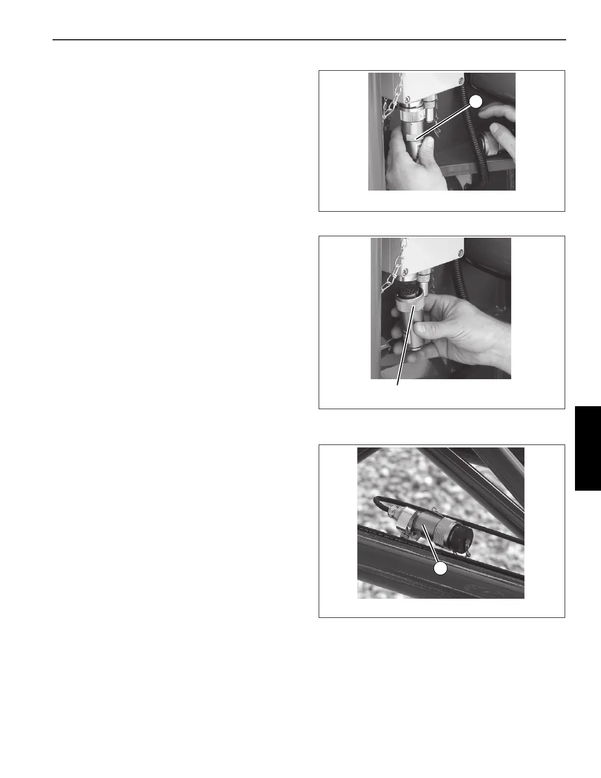
5. Disconnect RCL cable.
a. Remove connector (1, Figure 4-16) from junction
box on boom nose.
b. Install dummy plug (1, Figure 4-17) on junction box.
c. Route cable through boom extension and stow
connector (1, Figure 4-18).
6. If erected, stow the extension fly section as follows:
a. Attach a length of rope to the fly extension tip.
b. Raise the boom to horizontal.
c. Remove the retainer clip and attachment pin from
the anchor and attach fittings on the left side of the
base section and stow in the base section.
 Loading...


