Grove Published 4-09-2021, Control # 364-11 3-17
RT765E-2 OPERATOR MANUAL OPERATING CONTROLS AND PROCEDURES
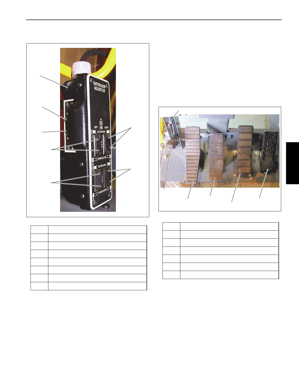
OUTRIGGER CONTROL
.
The Outrigger Control Box (1, Figure 3-11) is stowed in the
cab (Figure 3-1) and is used to control the outriggers from
inside the cab.
NOTE: The park brake must be engaged for the outriggers
to operate.
Extend/Retract Switch
The Extend/Retract Switch (6,7 Figure 3-11) is located on
the side of the Outrigger Control Box and is used in
conjunction with the Outrigger Selector Switches (2,3,4,5
Figure 3-11) to control the outrigger functions.
Outrigger Selector Switches
There are four Outrigger Selector Switches (2,3,4,5
Figure 3-11) on the Outrigger Control Box. To extend or
retract an outrigger component, first select the component
with the Outrigger Selector Switch (2,3,4,5), then select
extend or retract with the Extend/Retract Switch (6,7
Figure 3-11).
FOOT PEDAL CONTROLS
Figure 3-12 Item Numbers
360° Swing Lock Pedal
The 360° Swing Lock Pedal (1) (Figure 3-12) is located on
the left side of the crane cab floor. The pedal is used to
activate the swing lock to prevent the turret from turning. To
release the swing lock, pull up on the 360° Swing Lock
Release Lever (2).
Swing Brake Pedal
The Swing Brake Pedal (3) (Figure 3-12) is located on the
left side of the cab floor. The swing brake pedal is used to
Item Description
1 Outrigger Control Box
2 Right Front Extension/Jack Cylinder
3 Left Front Extension/Jack Cylinder
4 Right Rear Extension/Jack Cylinder
5 Left Rear Extension/Jack Cylinder
6 Retract O/R
7 Extend O/R
Item Description
1 360° Swing Lock Pedal
2 360° Swing Lock Release Lever
3 Swing Brake Pedal
4 Telescope Control Foot Pedal (Optional)
5 Service Brake Foot Pedal
6 Foot Throttle Pedal
 Loading...


