Grove Published 4-09-2021, Control # 364-11 4-1
RT765E-2 OPERATOR MANUAL SET-UP AND INSTALLATION
SECTION 4
SET-UP AND INSTALLATION
SECTION CONTENTS
General . . . . . . . . . . . . . . . . . . . . . . . . . . . . . . . . . . 4-1
Accessing the Hoist area (Fixed counterweight
units only) . . . . . . . . . . . . . . . . . . . . . . . . . . . . . . . . 4-1
Travel Configuration . . . . . . . . . . . . . . . . . . . . . . . 4-1
Working Position. . . . . . . . . . . . . . . . . . . . . . . . . . 4-2
Installing Cable on the Hoist . . . . . . . . . . . . . . . . . 4-2
Cable Reeving . . . . . . . . . . . . . . . . . . . . . . . . . . . . . 4-2
Boom Cable Reeving . . . . . . . . . . . . . . . . . . . . . . 4-3
Dead-End Rigging/Wedge Sockets . . . . . . . . . . . . 4-3
Installing Wedge and Socket . . . . . . . . . . . . . . . . 4-3
Anti Two Block (A2B) Switch. . . . . . . . . . . . . . . . 4-10
Lock . . . . . . . . . . . . . . . . . . . . . . . . . . . . . . . . . . 4-10
Unlock. . . . . . . . . . . . . . . . . . . . . . . . . . . . . . . . . 4-10
Before Operation . . . . . . . . . . . . . . . . . . . . . . . . 4-10
Erecting and Stowing the Bi-fold Boom
Extension . . . . . . . . . . . . . . . . . . . . . . . . . . . . . . . . 4-12
Erecting . . . . . . . . . . . . . . . . . . . . . . . . . . . . . . . . 4-12
Stowing the Swing-Away Boom Extension . . . . . 4-19
Setting the Folding Swingaway Offset . . . . . . . . . 4-21
Erecting and Stowing the Bi-fold Boom Extension
with the 20 ft (6.1 m) Insert . . . . . . . . . . . . . . . . . . 4-21
Erecting . . . . . . . . . . . . . . . . . . . . . . . . . . . . . . . . 4-21
Stowing . . . . . . . . . . . . . . . . . . . . . . . . . . . . . . . . 4-23
Fixed Counterweight . . . . . . . . . . . . . . . . . . . . . . . 4-24
Description. . . . . . . . . . . . . . . . . . . . . . . . . . . . . . 4-24
Maintenance . . . . . . . . . . . . . . . . . . . . . . . . . . . . 4-24
Removable Counterweight (Optional) . . . . . . . . . 4-26
Removal. . . . . . . . . . . . . . . . . . . . . . . . . . . . . . . . 4-26
Installation . . . . . . . . . . . . . . . . . . . . . . . . . . . . . . 4-26
GENERAL
This section provides procedures for installing the hoist
cable on the hoist drum, cable reeving, and erecting and
stowing the boom extension.
ACCESSING THE HOIST AREA (FIXED
COUNTERWEIGHT UNITS ONLY)
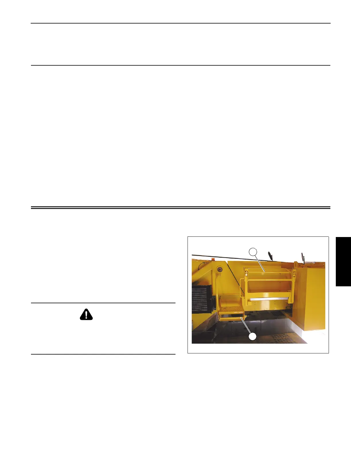
Configure the hoist access area from the Travel Position
(Figure 4-1) to the Working Position (Figure 4-2).
Travel Configuration
1. Railing (1) (Figure 4-1) is in the pinned and down
position.
2. Pull the step locking pin out, slide the step (2) in to the
travel position and release the lock pin to secure the
step in travel position.
DANGER
Platform must not be used for hauling passengers as
death or serious injury could occur.
No storage of components are allowed on the platform.
Only one person at a time is allowed on the platform.
 Loading...


