OPERATING CONTROLS AND PROCEDURES RT765E-2 OPERATOR MANUAL
3-2 Published 4-09-2021, Control # 364-11
Side Control Panel . . . . . . . . . . . . . . . . . . . . . . . . 3-15
Rated Capacity Limiter (RCL) and Work
Area Definition System Control Panel . . . . . . . . . 3-15
Rated Capacity Limiter (RCL) Bypass Switch . . . 3-15
Emergency Stop Switch . . . . . . . . . . . . . . . . . . . 3-15
Transmission Oil Temperature Gauge . . . . . . . . 3-15
Turntable Pin Swing Lock Control . . . . . . . . . . . . 3-15
12V Receptacle . . . . . . . . . . . . . . . . . . . . . . . . . . 3-16
Diagnostic Connector . . . . . . . . . . . . . . . . . . . . . 3-16
Bubble Level Indicator. . . . . . . . . . . . . . . . . . . . . 3-16
Hoist Third Wrap Indicator (Optional—Standard
on CE) . . . . . . . . . . . . . . . . . . . . . . . . . . . . . . . . . 3-16
Cold Weather Indicator (Optional). . . . . . . . . . . . 3-16
Telescope Cylinder Charge Indicator
(If Equipped) . . . . . . . . . . . . . . . . . . . . . . . . . . . . 3-16
Ambient Temperature LED Indicator. . . . . . . . . . 3-16
Outrigger Control . . . . . . . . . . . . . . . . . . . . . . . . . 3-17
Foot Pedal Controls . . . . . . . . . . . . . . . . . . . . . . . 3-17
360° Swing Lock Pedal . . . . . . . . . . . . . . . . . . . . 3-17
Swing Brake Pedal . . . . . . . . . . . . . . . . . . . . . . . 3-17
Telescope Control Foot Pedal (Optional) . . . . . . 3-18
Service Brake Foot Pedal . . . . . . . . . . . . . . . . . . 3-18
Foot Throttle Pedal . . . . . . . . . . . . . . . . . . . . . . . 3-18
Miscellaneous Controls and Indicators . . . . . . . 3-18
Fuse Panel . . . . . . . . . . . . . . . . . . . . . . . . . . . . . 3-18
Buzzer . . . . . . . . . . . . . . . . . . . . . . . . . . . . . . . . . 3-18
Rated Capacity Limiter (RCL) Emergency Override
Switch (Non-CE Certified Cranes) . . . . . . . . . . . . 3-18
Rated Capacity Limiter (RCL) Emergency Override
Switch and Indicator (CE Certified Cranes) . . . . . 3-19
Rated Capacity Limiter (RCL) Internal Light
Bar (Optional). . . . . . . . . . . . . . . . . . . . . . . . . . . . 3-19
Strobe Light or Beacon (Optional) (Not Shown). . 3-19
Backup Alarm (Not Shown) . . . . . . . . . . . . . . . . . 3-19
Emergency Exit . . . . . . . . . . . . . . . . . . . . . . . . . . 3-20
Operating Procedures . . . . . . . . . . . . . . . . . . . . . . 3-20
Pre-Starting Checks . . . . . . . . . . . . . . . . . . . . . . . 3-20
Cold Weather Operation . . . . . . . . . . . . . . . . . . . 3-21
Crane Warm-up Procedures . . . . . . . . . . . . . . . . . 3-23
Above 95°C (200°F): No crane operation is allowed.
Let hydraulic oil cool by running engine at idle with no
functions actuated. . . . . . . . . . . . . . . . . . . . . . . . . 3-24
Engine Operation . . . . . . . . . . . . . . . . . . . . . . . . . 3-24
Jump Starting Hazard . . . . . . . . . . . . . . . . . . . . . 3-24
Charging the Batteries . . . . . . . . . . . . . . . . . . . . . 3-24
Transporting the Crane . . . . . . . . . . . . . . . . . . . . 3-27
Crane Travel Operation . . . . . . . . . . . . . . . . . . . . 3-27
Traveling on Slopes . . . . . . . . . . . . . . . . . . . . . . . 3-29
General Crane Operation. . . . . . . . . . . . . . . . . . . 3-35
Stowing and Parking . . . . . . . . . . . . . . . . . . . . . . 3-41
Unattended Crane . . . . . . . . . . . . . . . . . . . . . . . . 3-42
CONTROLS AND INDICATORS
The engine is electronically controlled by the Electronic
Control Module (ECM); it is the control center of the entire
engine system. The ECM processes all of the inputs and
sends commands to the fuel systems as well as vehicle and
engine control devices. This Operator Manual does not
include information on the engine ECM, however a separate
manual as prepared in detail by the engine manufactured is
shipped with the crane at the factory.
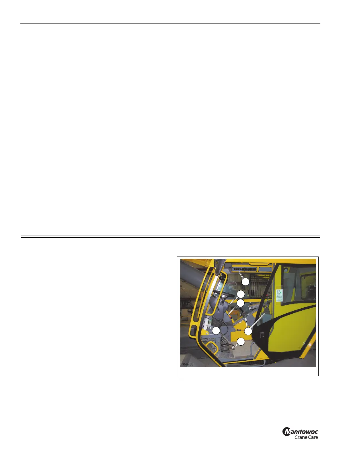
All the controls and indicators to operate and monitor crane
functions are found inside the crane cab Figure 3-2 and
include the following:
1. Foot Pedals
2. Outrigger Control
3. Seat Joystick and Armrest Controls
4. Side Display Panel
5. Steering Column
6. Overhead Control Panels
STEERING COLUMN
The steering column assembly in Figure 3-2 is a pedestal
style tilt and telescoping steering column. It has the ability to