SET-UP AND INSTALLATION RT765E-2 OPERATOR MANUAL
4-26 Published 4-09-2021, Control # 364-11
REMOVABLE COUNTERWEIGHT
(OPTIONAL)
NOTE: The removable counterweight consists of one
standard box. The following procedures are
applicable for removal and installation of any or all
pieces.
Removal
1. Position the crane on a firm level surface. Fully extend
and set the outriggers.
2. Rotate the superstructure to align the counterweight with
the support weld on the front outrigger box. Engaging
the pin type turntable lock will aid alignment.
NOTE: It may be necessary to jog the counterweight
removal control valve switches to remove the
weight of the counterweight from the upper attach
pins.
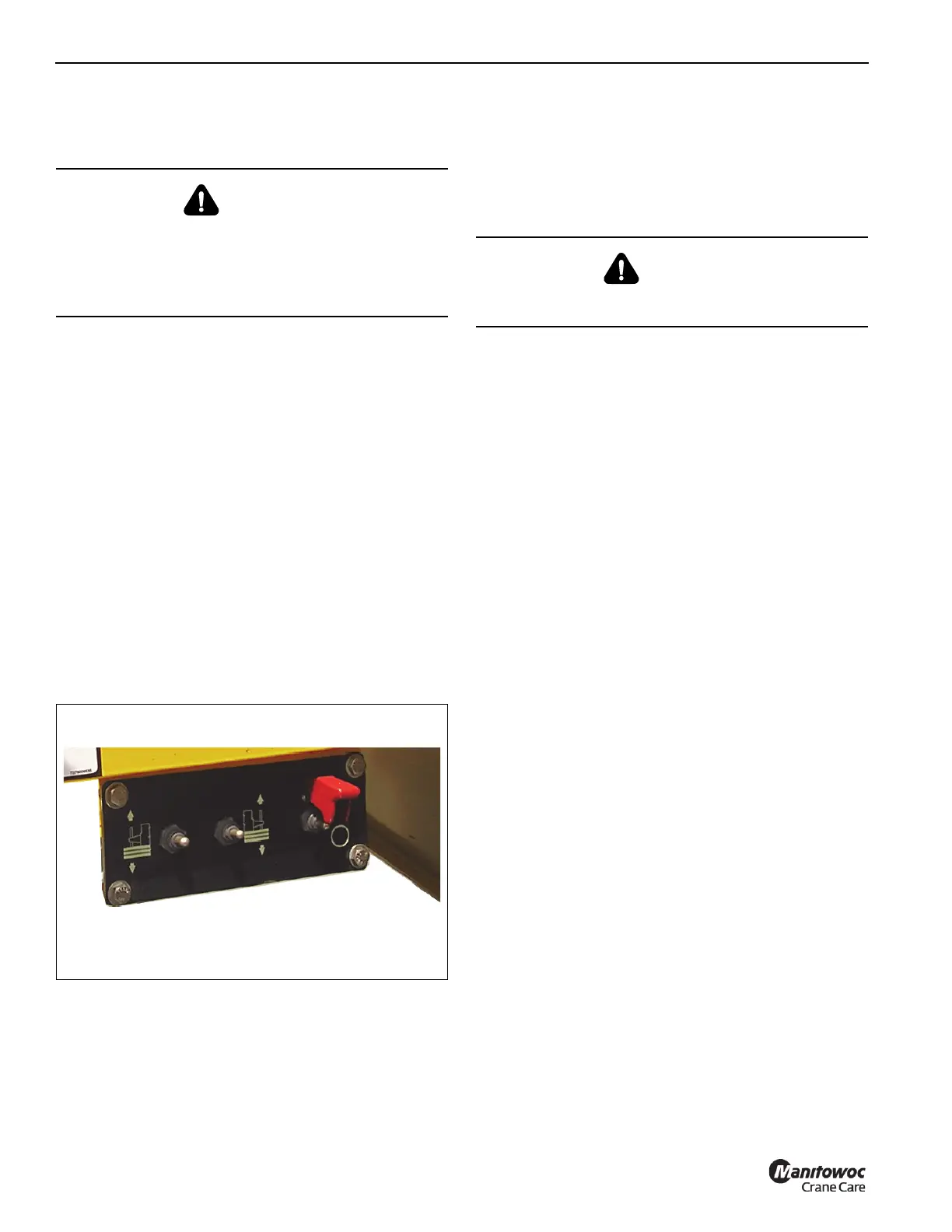
3. Using the counterweight removal control valve switches
(Figure 4-22), raise the counterweight cylinders to
relieve weight on the upper attach pins.
4. Push in, turn, and remove the upper attach pins from the
superstructure frame lugs and the counterweight.
5. Stow the upper attach pins in the bushings on the side of
the superstructure.
6. Using the counterweight removal control valve switches,
slowly lower the counterweight onto the carrier stowage
area.
7. Remove the attach pins from the counterweight lugs and
cylinder ends. Raise the cylinders and stow the attach
pins in cylinder and insert retainer clip pins.
NOTE: The counterweight weighs approximately 14,860 lb
(6740 kg).
8. Remove counterweight from the support weld on the
front outrigger box before moving crane.
9. Using the crane’s boom and hoist or other crane, lift the
counterweight from the carrier deck to the auxiliary
transport vehicle.
Installation
1. Position the crane on a firm level surface. Fully extend
and set the outriggers.
2. Select the proper without counterweight operating code
on the RCL.
NOTE: The counterweight weighs approximately 6740 kg
(14,860 lb).
3. Using the crane’s boom and hoist or other crane, lift the
counterweight from the auxiliary transport vehicle and
position the counterweight.
4. Rotate and align the rear of the superstructure above the
removable counterweight setting on the support weld on
the front outrigger box. Engaging the pin type turntable
lock will aid alignment.
5. Using the counterweight removal control valve switches
(Figure 4-22) and (Figure 4-23) located on either side of
the turntable, lower the counterweight cylinders. Pin the
cylinders to the counterweight using the attach pins in
the cylinders. Insert the retaining pins in the attach pins.
6. Using the control switches, raise the counterweight up
under the superstructure frame.
NOTE: It may be necessary to jog the counterweight
removal control valve switches to install the upper
attach pins.
7. Remove the upper attach pins from the stowage
bushings and install them into the upper counterweight
and superstructure frame lugs.
8. Push in on the pins and turn to lock pin in the notch.
DANGER
Death or serious injury could result from being crushed by
a falling counterweight.
Ensure that all mounting pins are properly installed and
locked, during, and after operating the counterweight
removal system.
FIGURE 4-22
7889-2
Valve Control
Switches
DANGER
Travel is not permitted with the removable counterweight
on the carrier deck.
 Loading...


