Grove Published 4-09-2021, Control # 364-11 3-7
RT765E-2 OPERATOR MANUAL OPERATING CONTROLS AND PROCEDURES
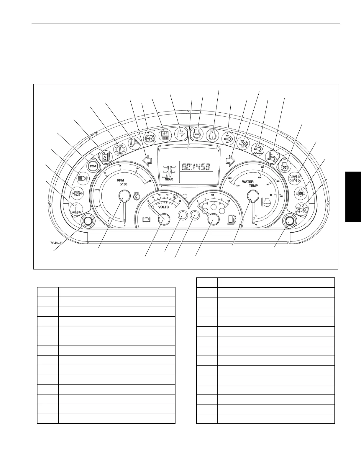
STEERING COLUMN INDICATOR AND
GAUGE DISPLAY
As a system check, the indicators will come on for two
seconds when the Ignition Switch is turned to the RUN
position.
Figure 3-6 Item Numbers
3
2
1
6
5
4
7
8
12
11
10
9
15
14
13
19
18
17
20
16
22
21
23
24
29
25
31
30
26
28
27
FIGURE 3-6
Item Description
1 Swing Brake Engaged
2 Parking Brake Engaged
3 Light Malfunction
4 Emergency Stop
5 Hydraulic Oil High Temperature
6 Transmission Warning
7 Low Steer Pressure
8 Left Turn Signal
9 Low Service Brake Pressure
10 Electronic Module Control
11
Electrical System Diagnostics
12 LCD Display
13 Engine Stop
14 Engine Warning
15 DPF, Regeneration Required
16 Right Turn Signal
17 Inhibit Regeneration
18 Not Used
19 High Exhaust System Temperature
20 Engine Wait to Start
21 Four-Wheel Drive Engaged
22 Axle Differential Locked
23 Rear Wheels Not Centered
24 Push Button Switch (not used)
25 Engine Coolant Temperature Gauge
26 Fuel Gauge
27 Low Fuel Level Indicator
Item Description
 Loading...


