OPERATING CONTROLS AND PROCEDURES RT765E-2 OPERATOR MANUAL
3-4 Published 4-09-2021, Control # 364-11
Test Mode Switch
The Test Mode Switch (7) (Figure 3-2) is used when
servicing the engines electronic control system. It is a two
position on/off rocker switch used to activate the diagnostic
mode (fault codes). The ignition switch must be ON but the
engine not running. When the Test Mode Switch is ON, and
is used in conjunction with the Idle/Diagnostic Mode Switch,
access will be gained to scroll up or down through the fault
codes.
Idle/Diagnostic Mode Switch
The Idle/Diagnostic Mode Switch (8) (Figure 3-2) is a three
position (+/-) momentary rocker switch that provides idle-
control inputs that increases and decreases the engine idle
(when the Test Mode Switch is in the OFF position) or scrolls
up or down though the diagnostic mode fault codes when the
test mode switch is in the ON position with the engine not
running.
Press and release the top of the switch once to increase the
engine to high idle. Press and release the bottom to return to
low idle. Press and hold the switch, release when a
predetermined idle speed is reached. Press the bottom to
return to low idle.
Ignition Switch
The Ignition Switch (9) is located on the right side of the
steering column and under the transmission shift lever(10).
The switch is key-operated and has four positions: ACC [3],
OFF [0], RUN [1], and START [2]. In the OFF position, all
electrical power is off except for the lights controlled by the
Headlights Switch, turn/hazard/stop lights, dome light and
work light. Positioning the switch to ACC energizes all
electrical components except for the start solenoid and
engine ECM. Positioning the switch to RUN is the same as
ACC, but the ignition circuit is also energized. Positioning the
switch to START energizes the start relay, which in turn
energizes the cranking motor solenoid and cranks the
engine for starting. The switch is spring returned from
START to RUN. To shut down the engine, position the switch
to OFF.
The Ignition switch has a mechanical anti-restart built into it.
If the engine does not start after the first attempt, the key
switch must go to the OFF position and then back to START
in order to try and start the engine another time.
Transmission Shift Lever
The Transmission Shift Lever (10) (Figure 3-2) is located on
the right side of the steering column. The control lever
operates the transmission selector valve electrically.
Positioning the lever up actuates forward and positioning the
lever down actuates reverse. When the lever is in neutral, it
rests in a detent. To move the lever up or down, pull back on
the lever first. To shift the transmission to first, second, or
third gear, rotate the knob to 1, 2, or 3.
The transmission has six forward gears and six reverse
gears. To use the three low gears, put the Drive Axle switch
at 4WD LO. To use the three high gears, put the Drive Axle
switch at 2WD HI.
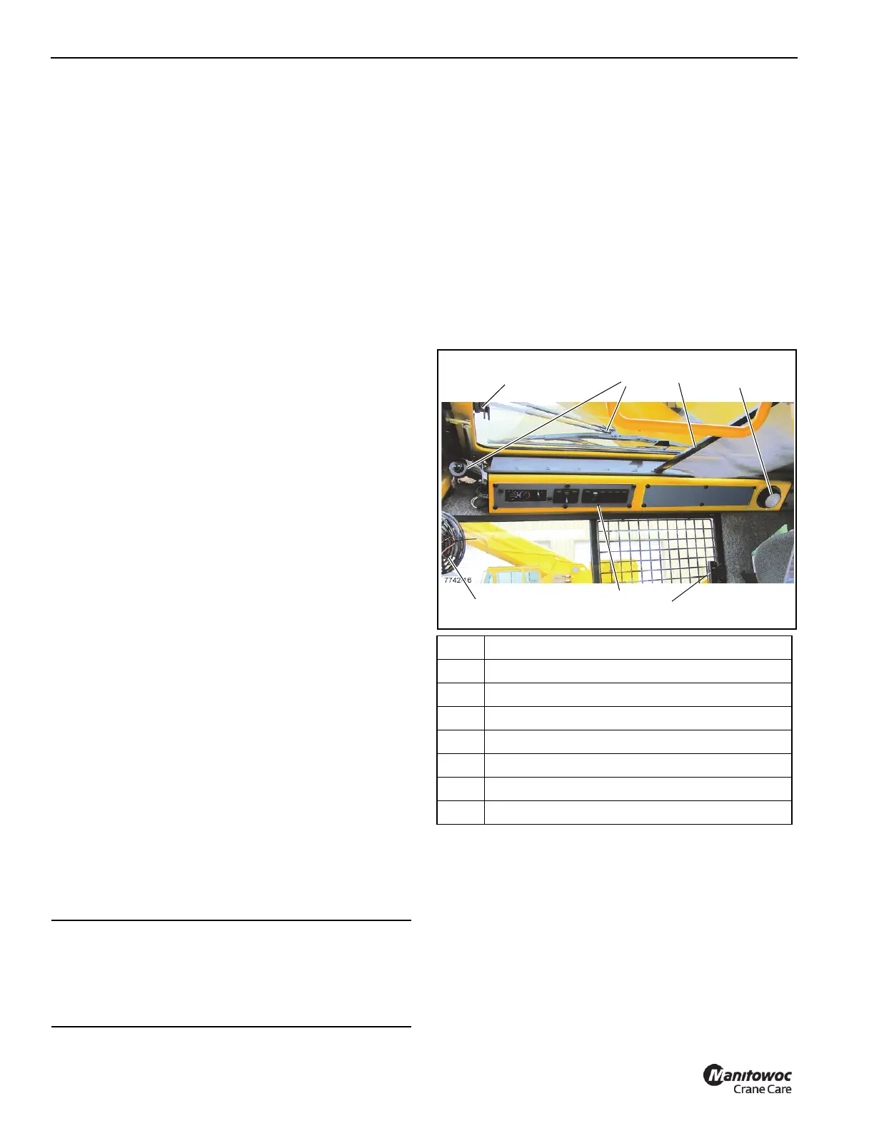
CAB OVERHEAD CONTROLS
.
Skylight Window Latch
The Skylight Window Latch (1, (Figure 3-3)) is at the front of
the window. Squeeze the latch and slide the window to the
rear to open. to close slide the window forward until the latch
engages.
Skylight Wiper and Wiper Motor
The Skylight Wiper (2, Figure 3-3) is controlled by the
Skylight Wiper Switch, (4) (Figure 3-4), and operated by the
Wiper Motor.
CAUTION
Transmission Damage!
To prevent transmission damage: shift between two-
wheel and four-wheel drive only with the crane stopped
with the transmission in neutral or park.
Item Description
1 Skylight Window Latch
2 Skylight Wiper & Motor
3 Skylight Sunscreen
4 Dome Light
5 Cab Circulating Fan
6 Window Latch
7 Overhead Control Panels
 Loading...


