5-2 3-29-2018 Control # 610-00
OPERATING CONTROLS - AERIAL LIFT NBT40-1 SERIES OPERATOR MANUAL
Power Take Off
The power take off (PTO) must be engaged for aerial lift
operations. For operation instructions refer to, Power Take
Off, page 4-2.
OUTRIGGERS
Outrigger Controls - Aerial Lift
The Outrigger Controls are used to set the outriggers.
Outriggers must be controlled from ground stations. For
operation instructions of the Outrigger Controls refer to,
(Outrigger Controls, page 4-2.)
Outrigger Monitoring System (OMS)
The Outrigger Monitoring System (OMS) aids the operator in
accurately programming Rated Capacity Limiter (RCL) by
automatically identifying position of each outrigger beam.
OMS uses four sensors, one per outrigger beam, and an
inclinometer located in the aerial lift superstructure to identify
when an outrigger beam is fully extended or an outrigger jack
is extended. This system is standard equipment on all aerial
lifts. Status will display on the RCL screen in ground control
cab (Figure 4-3) when an outrigger beam is positioned to
one of pre-defined locations, including fully retracted, mid-
extend, or fully extended.
Set up of the outriggers is same for cranes equipped with
OMS, (See “Setting the Outriggers” on page 4-17.)
Outrigger Jack Monitoring System
The outrigger jack monitoring system is equipped with the
Aerial Lift option and is functional during both crane and
aerial lift operating modes. Refer to, (Outrigger Jack
Monitoring, page 4-18.)
Leveling of the Aerial lift
It is essential that the aerial lift is level to within 1% of grade.
The bubble level that is provided on the aerial lift is calibrated
to be accurate within 1% of grade. If equipment is out of
level, an audible alarm will beep indicating releveling is
necessary. To properly level the aerial lift, refer to Leveling of
Equipment, page 4-6.
A working aerial lift may settle during operations. Frequently
check the aerial lift for level. When rechecking the aerial lift
for level, the boom must be positioned over the front of the
aerial lift, fully lowered to horizontal and fully retracted. For
an aerial lift fitted with a boom rest, the boom shall be stowed
onto the boom rest.
Equipment Level Indicators
For leveling operation instructions refer to,Equipment Level
Indicators, page 4-7.
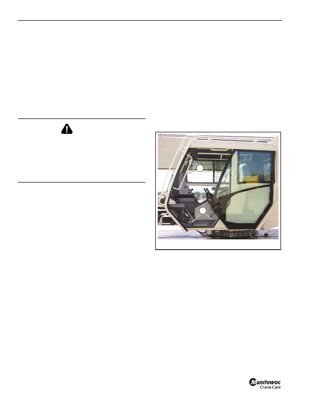
EQUIPMENT GROUND CONTROLS
The equipment ground controls are located in the Ground
Controls station (operator’s cab) Figure 5-2 and are used for
equipment functions.
See (Figure 4-3) for component identification. For best
control response, run the engine at governed RPM when
operating the equipment.
NOTE: The crane control power switch (20, Figure 4-3)
located on the right overhead console must be
activated.
NOTE: When the radio remote control is activated, all
crane ground controls will be deactivated.
The ground controls are designed to override the boom and
work platform positioning functions of the aerial platform
controls. The ground controls are used to setup the
outriggers and to position the boom to equip either the
personnel platform or jib for use.
Perform all pre-start inspections and test from the ground
controls, (Reference Pre-Start Functional Test, page 9-2)
except inspection and test of platform controls.
DANGER
Tipping Hazard!
To avoid death or serious injury ensure that the aerial lift is
level in order to maintain stability.
Position aerial lift on a firm surface, fully extend outriggers
and level equipment. All four outrigger beams must be
deployed to fully extended; do not operate the aerial lift
with the outriggers in any other position.

 Loading...


