National Crane 3-29-2018 Control # 610-00 4-9
NBT40-1 SERIES OPERATOR MANUAL OPERATING CONTROLS - CRANE
Swing Brake Pedal
Swing brake pedal (2, Figure 4-3) is located on the left side
of the crane cab floor. Brake pedal is used to activate swing
brake and momentarily hold turret in position.
Boom Telescope Pedal (if equipped)
Telescope foot pedal (3, Figure 4-3) is used to extend and
retract boom when equipment is equipped with an auxiliary
hoist. Rock pedal forward to extend boom and rock back to
retract boom.
Foot Throttle Pedal
Foot throttle (4, Figure 4-4) is located on ground control cab
floor and is used to control engine speed. Depress foot
throttle to accelerate engine speed and release to return to
idle.
Hand throttle (11, Figure 4-3) must be positioned as
indicated in Figure 4-6 to operate foot throttle properly.
RCL Display
RCL Display (5 Figure 4-3) is for Rated Capacity Limiter
(RCL), see operating instructions and screen displays in this
manual.
RCL provides crane operator with information required for
crane to perform safely within its design parameters. RCL
displays information on length and angle of boom, working
radius, rated load, and total weight being lifted.
RCL continuously monitors these parameters and provides
operator with an updated readout of equipment status. If a
nonsafe condition is approached, RCL warns operator with
an alarm and locks out crane functions that can aggravate
situation.
7462-5b
7462-4
FIGURE 4-4
29
30
31
32
33
34
17
38
35
37
36
39
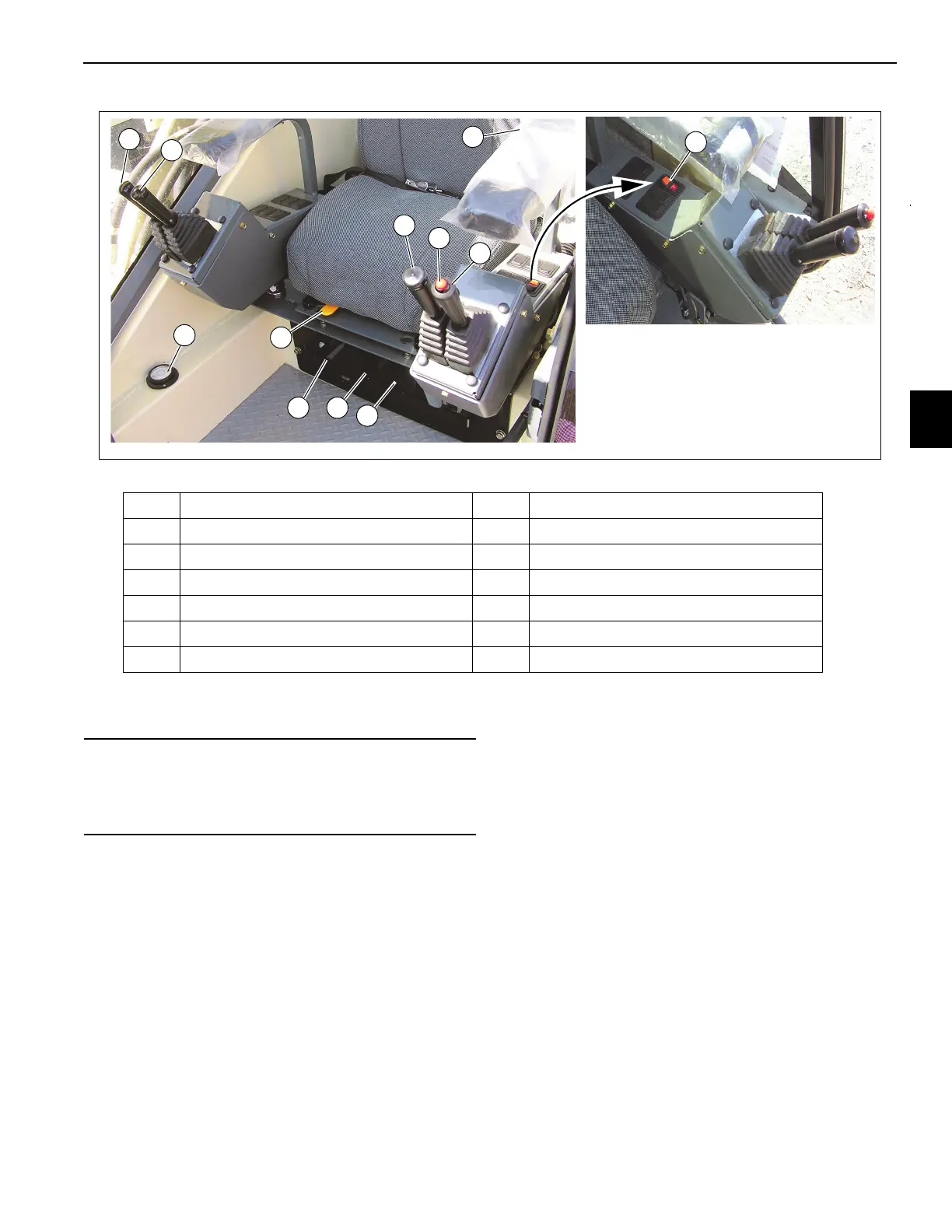
Item Description Item Description
29
Boom Lift Control Lever
35
Seat Slide Handle
30
Hoist Up & Down Control (Rotation Indicator) 36 Seat Frame Slide Handle
31
Telescope Boom (Auxiliary Hoist Control) 37 Climate Control Unit
32
Warning Horn Button 38 Level
33
Turret Swing Control Lever 39 Swing Lock Control Switch
34
Seat Back Adjustment 40 House Lock (Figure 3-3)
CAUTION
Do not actuate the Swing Control Lever while the Swing
Brake is engaged, as the turret may push through the
brake. Damage to the swing brake can occur.

 Loading...


