HOIST NBT40 SERVICE MANUAL
5-4 Published 8-01-2017 Control # 287-11
6. worn or damaged; replace it.
Hoist Rotation Indicator (HRI) Display
System
The HRI Display consists of an LED display that indicates
the direction the hoist(s) are rotating, pressure switches that
monitor hydraulic pilot pressure, and a control module
mounted in the cab. The HRI system also provides the
operator with a touch indication of drum rotation so he will
know if and at what speed the hoist drum is rotating, even
under the most distracting conditions. (See “Drum Rotation
Indicator” on page 5-5 DRI).
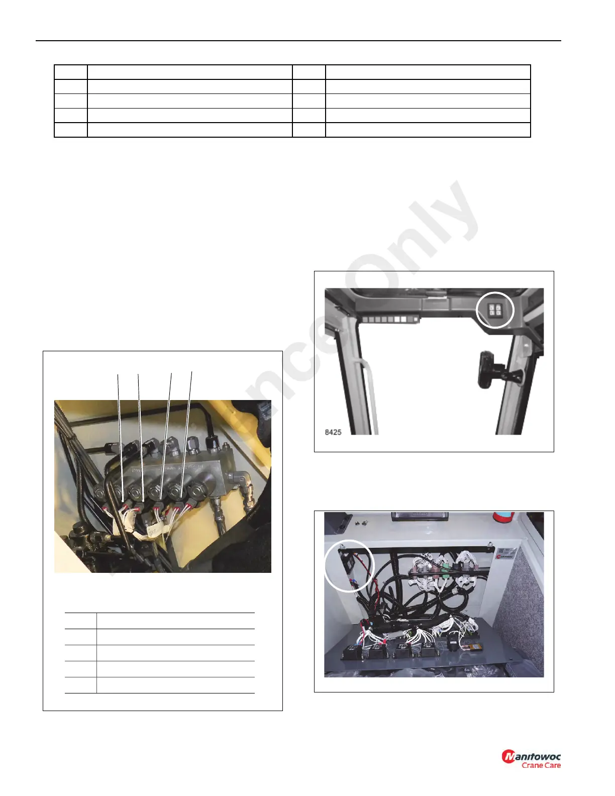
Pressure Switches
The pressure switches are located on the main control valve
Figure 5-2. The switch contacts close at 75 psi (5.17 bar).
HRI Display
The display is located in the front overhead panel Figure 5-3.
To replace the display, remove the overhead panel.
Disconnect the electrical connector and pry the display off of
the panel. Clean the panel where the display was affixed with
isopropyl alcohol, remove the paper from the adhesive back
of the new display and stick it into the panel. Connect the
wires to the display. Replace the panel and secure with the
hardware.
HRI Control Module
The control module is located in the fuse and relay panel
behind the driver’s seat in the cab Figure 5-4.
To replace the control module, tag and disconnect the wires
from the module Figure 5-5. The module is mounted to the
17 Tube, Lower 21 Elbow, 90
18 Tube, Raise 22 Brake
19 Adapter 23 Case Drain Hose
20 Motor 24 Elbow, 90
Item Component Item Component
FIGURE 5-2
8425-9
Item Description
1 Main Hoist Down Switch
2 Auxiliary Hoist Down Switch
3 Auxiliary Hoist Up Switch
4 Main Hoist Up Switch
1
TYPICAL
VIEW ONLY
4
3
2
Reference Only

 Loading...


