National Crane Published 8-01-2017 Control # 287-11 9-25
NBT40 SERVICE MANUAL CRANE INSTALLATION
Truck Interface Electrical Connection
Connections to the truck electrical system is as follows:
NOTE: Keep the harness away from the drive line and
exhaust system.
• The accessory and ignition wires are tied into the back of
the ignition switch in the truck cab.
• If there are two ignition wires when tying into the truck
ignition, tie into both wires.
• Be sure the wires are not pinched or cut.
8
5
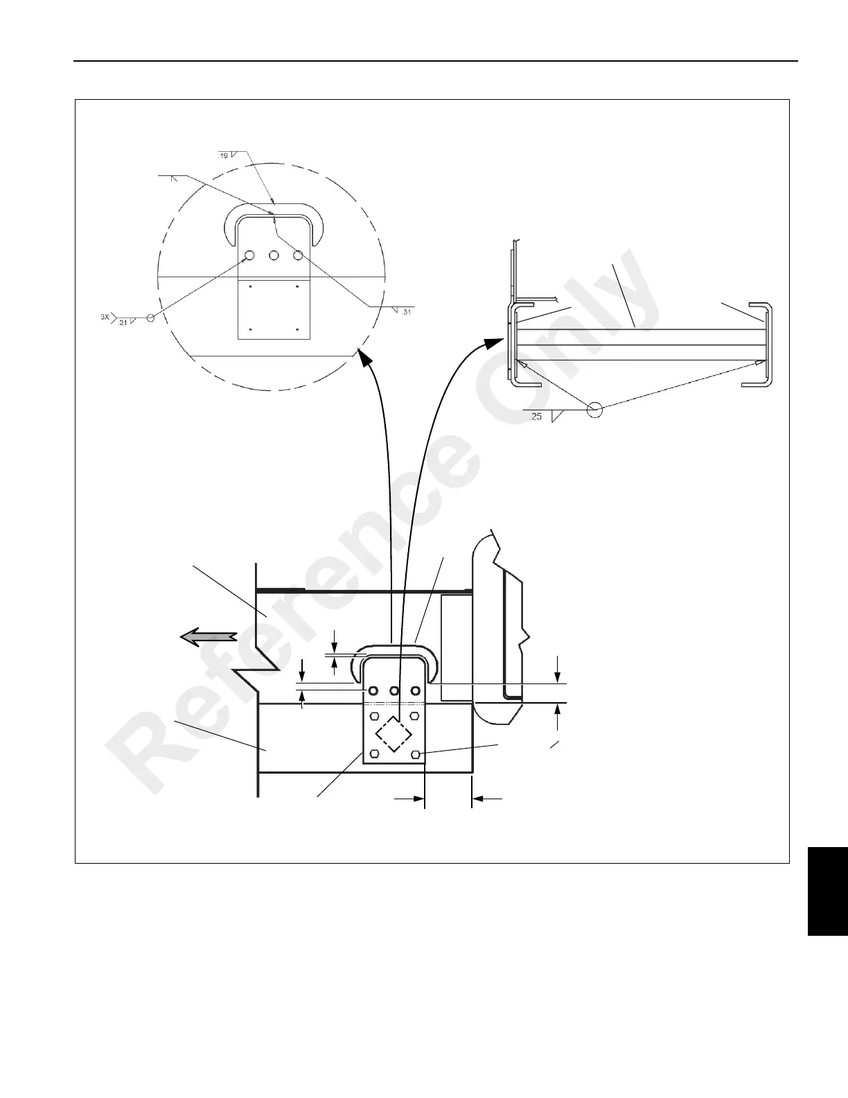
FIGURE 9-16
11
1 in
(254 mm)
No Weld
0.38 in
(380 mm)
7.5 in (19 cm)
10
7
6
11
7610-5
76010-6
C
9 (4, 5/8” O)
Reference Only

 Loading...


