HYDRAULIC SYSTEM NBT40 SERVICE MANUAL
2-20 Published 8-01-2017 Control # 287-11
Table 2-1 Pressure Settings
Pump Margin Pressure Setting
1. Install a gauge at the pump pressure gauge port (2) on
the Main Directional Control Valve Manifold,
Figure 2-14.
2. Idle engine with PTO engaged and do not operate any
functions.
3. Verify margin pressure is 25.8 bar ±3.4 bar (375 psi
±50 psi).
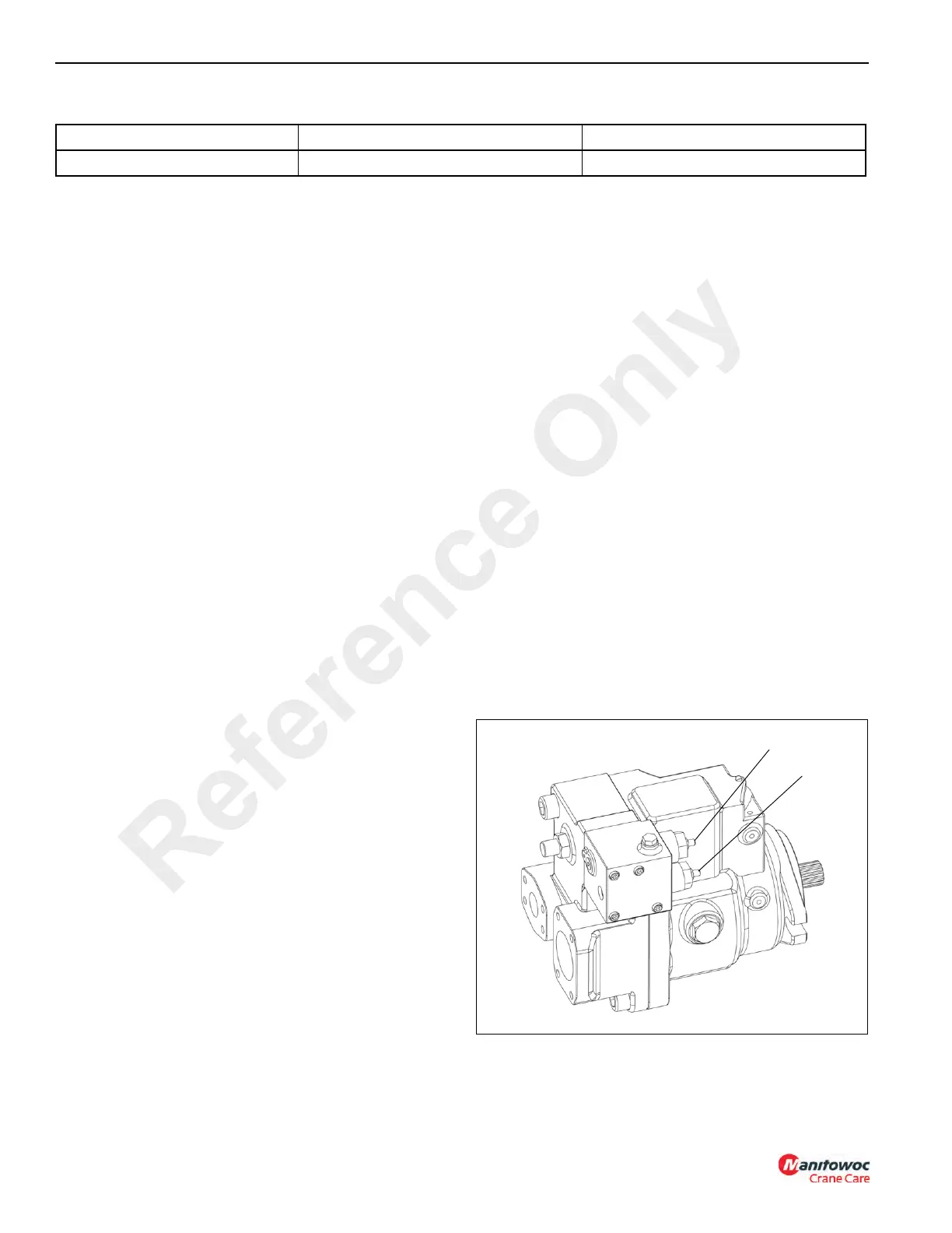
If margin pressure is not correct, adjust Load Sense (LS)
Adjusting Screw (2, Figure 2-13) at pump. Turn screw
(2) clockwise to increase the setting; each turn gains
18.9 bar (275 psi). Tighten lock nut 12 lb-ft to secure the
setting.
Maximum Pump Pressure Setting
Install a gauge at the pump pressure gauge port (2) on the
Main Directional Control Valve Manifold, Figure 2-14.
Crane Preparation
1. Prepare the crane to check the maximum pump
pressure setting by doing one of the following:
2. Start engine and engage PTO.
3. Raise boom to its maximum elevation or cap both boom
hoses.
4. Activate boom up to increase pump pressure to
maximum setting.
Adjust Maximum Pressure
1. Idle engine with PTO engaged.
2. Verify maximum pump pressure is at correct settings
(see Table 2-1, “Pressure Settings,” on page 20).
3. If maximum pressure is incorrect, adjust Pressure
Compensating (PC) adjusting screw.
• Loosen locknut and turn PC adjustment screw (1,
Figure 2-13) clockwise to increase the setting; each turn
gains 99.9 bar (1450 psi). Tighten lock nut 16.2 nm
(12 lb-ft) to secure setting.
• Reset the LSRV setting (see Load Sense Relief Valve
Pressure Setting).
Load Sense Relief Valve Pressure Setting
1. Perform this procedure after setting the pump’s
maximum pressure setting or checking the Load Sense
Relief Valve
(LSRV) setting.
Method #1
Leave the main hoist up/down hoses connected to the motor.
Remove and cap the main hoist brake line at the hoist down
block on the hoist. Activate the hoist down function to
develope pressure.
Method #2
Disconnect and cap and plug the main hoist up/down hoses.
Activate the hoist up and down function to develope
pressure.
Set the LSRV Pressure
• Idle engine with the PTO engaged.
• Use method #1 or #2 and hold the joystick controller.
Verify the LSRV pressure is at correct setting (see
Table 2-1, “Pressure Settings,” on page 20).
• If LSRV pressure is not correct, adjust LSRV adjusting
screw. Loosen locknut and adjust the setting. Turn PC
adjustment screw (1, Figure 2-13) clockwise to increase
the setting; each turn gains 58.6 bar (850 psi). Tighten
lock nut 5.4 nm (4 lb-ft) to secure setting.
Pump Margin Pressure Maximum Pump Pressure Load Sense Relief Valve Pressure
25.8 bar ±3.4 bar (375 psi ±50 psi) 310 bar -0 +3.4 bar (4500 psi -0+50 psi) 287.8 bar ±6.8 bar (4175 psi ±100 psi)
Reference Only

 Loading...


