HYDRAULIC SYSTEM NBT40 SERVICE MANUAL
2-12 Published 8-01-2017 Control # 287-11
RELIEF VALVE PRESSURE SETTING
PROCEDURES
Description
The valves in the hydraulic system must be properly
adjusted to protect a component, circuit, or system from over
pressurization (relief valves) and ensure the components
receive the appropriate pressure and flow.
Maintenance
Relief valves are checked and adjusted by causing a given
circuit to reach its prescribed pressure limit (stall). At this
point the relief valve opens, returning hydraulic oil to the
reservoir. Hydraulic motor circuits can be stalled by
preventing rotation of the motor shaft prior to actuating the
control valve. Cylinder circuits can be stalled by extending or
retracting a cylinder to its limit of travel.
Correct relief valve adjustment is mandatory for proper
functioning of a hydraulic circuit. Only qualified technicians
using the correct equipment should make pressure
adjustments when pressure adjustments are needed.
NOTE: Use an accurate 0 to 34,500 kPa (0 to 5000 psi)
pressure gauge when adjusting relief valves. To
adjust a relief valve, turn the adjustment screw (in
to increase or out to decrease) until the proper
setting is reached.
Release the control lever after taking each reading
and while making adjustments. When the proper
pressure setting has been attained, tighten the
adjustment screw locknut and recheck the
pressure.
It is only necessary to hold hydraulic pressure long
enough (usually a few seconds) to gain an
accurate reading. Do not overload the hydraulic
circuits for long periods of time.
Reservoir oil temperature is to be 140° - 160°F.
Preparation
• Run the engine until the hydraulic oil temperature
reaches a minimum of 49°C - 60°C (120°F - 140° F).
• Shut down the engine.
Relief Valve Pressure Settings
CAUTION
Do not overtighten the adjustment screw or locknut.
Do not hold the relief valve open for more than one minute
at a time.
DANGER
Do not attempt to loosen the fittings in pressurized lines or
while the hydraulic pumps are in operation or personnel
injury could result.
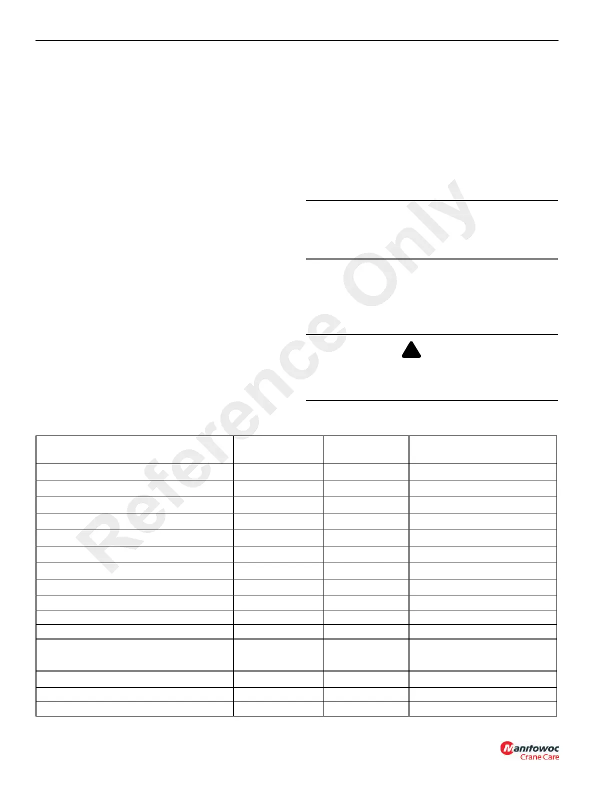
Valve To Be Set
Pressure Setting
kPa (PSI)
Tolerance kPa
(PSI)
Valve Adjustment Location
Telescope Retract Relief 15513 (2250) ±689 kPa (100 psi) Main Control Valve
Telescope Extend Relief 18615 (2900) ±689 kPa (100 psi) Main Control Valve
Load Sense Relief 28785 (4175) ±344 kPa (50 psi) Main Control valve
Outrigger Relief (Flow Control Valve) 20684 (3000) ±689 kPa (100 psi) Front Outrigger Box
Boom Up Relief 24821 (4550) ±344 kPa (50 psi) Main Control Valve
Boom Down Relief 6894 (1000) ±689 kPa (100 psi) Main Control Valve
Front Stabilizer Extend (if equipped) 3447 (500) ±689 kPa (100 psi) Port Block on Front Stabilizer
Front Stabilizer Retract (if equipped) 12065 (1750) ±689 kPa (100 psi) Port Block on Front Stabilizer
System Stand-by Pressure 2585 (375) ±344 kPa (50 psi) Main Control Valve
Main/Aux Hoist Raise & Lower 29647 (4300) ±689 kPa (100 psi) Main Control Valve
System/Boom Up Relief 31026 (4550) ±689 kPa (100 psi) Main Control Valve
Swing Valve Relief (CW/CCW) 21373 (3100)
+689 kPa (200 psi)
-0 PSI
Swing Control Valve
Air Conditioning Relief Valve 25855 (3750) ±689 kPa (100 psi) Swing Control Valve
Front Stabilizer Extend (if equipped) 3447 (500) ±689 kPa (100 psi) Front Stabilizer
Front Stabilizer Retract (if equipped) 12065 (1750) ±689 kPa (100 psi) Front Stabilizer
Reference Only

 Loading...


