National Crane Published 8-01-2017 Control # 287-11 3-5
NBT40 SERVICE MANUAL ELECTRIC SYSTEM
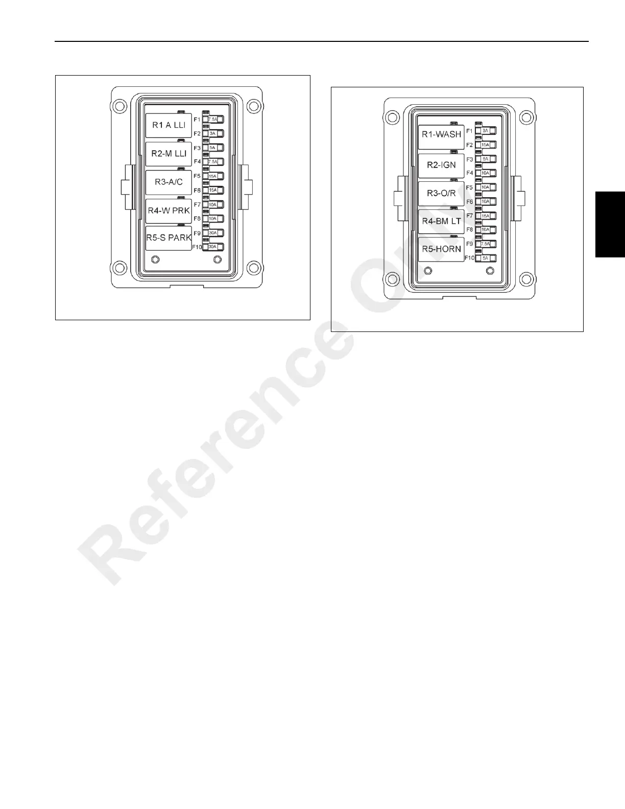
Fuse Box #1
Micro Relay Fuse Box #1
The micro relay fuse block (4, Figure 3-2) is located on the
left side of the fuse relay panel and contains the following
components, see Figure 3-3:
• R1 - Auxiliary Hoist Minimum Wrap Indictor (MWI) circuit
• R2 - Main Hoist Minimum Wrap Indicator (MWI) circuit
• R3 - Air Conditioner Power Relay
• R4 - Windshield Wiper and Park Switch
• R5 - Skylight Wiper and Park Switch
• F1- Spare - Crane/Remote Power Relay
• F2 - Windshield Wiper Circuit - 3 amp
• F3 - Spare - 5 amp
• F4 - Crane/remote Power Relay and Crane Power
Switch - 7.5 amp
• F5 - Air Condition Power Relay - 15 amp
• F6 - RCL Power and Override Switch, Circulation Fan
Switch - 15 amp
• F7 - Horn, Horn Relay and Horn Switch - 10 amp
• F8 - Heater and Air Conditioner Controls - 10 amp
• F9 - Spare - 30 amp
• F10 - HVAC Power Relay - 30 amp
Fuse Box #2
Micro Relay Fuse Box #2
The micro relay fuse block (5, Figure 3-2) is located in the
middle of the fuse relay panel and contains the following
components, see Figure 3-4:
• R1 - Washer Relay
• R2 - Ignition Relay
• R3 - Outrigger Control Relay
• R4 - Boom Lights Relay
• R5 - Horn Relay
• F1- Washer Relay - 3 amp
• F2 - Cab Work Lights, Cab Fan- 15 amp
• F3 - Spare - 5 amp
• F4 - Windshield Wiper - 10 amp
• F5 - RCL Power -10 amp
• F6 - Skylight Wiper - 10 amp
• F7 - Boom Lights - 15 amp
• F8 - 12V Charger - 10 amp
• F9 - Horn - 7.5 amp
• F10 - Seat Switch- 5 amp
Reference Only

 Loading...


