National Crane Published 8-01-2017 Control # 287-11 9-5
NBT40 SERVICE MANUAL CRANE INSTALLATION
Gross Vehicle Weight Rating (GVWR) is dependent on all
components of the vehicle (axles, tires, springs, frame, etc.)
meeting manufacturers' recommendations; always specify
GVWR when purchasing trucks.
Diesel engines require a variable speed governor and
energize-to-run fuel solenoid for smooth crane operation;
electronic fuel injection is required.
All mounting data is based on a National Series NBT40 with
subbase and an 85 percent stability factor.
The complete unit must be installed in accordance with
factory requirements, and a test performed to determine
actual stability and counterweight requirements; contact the
factory for details.
Transmission neutral safety interlock switch is required.
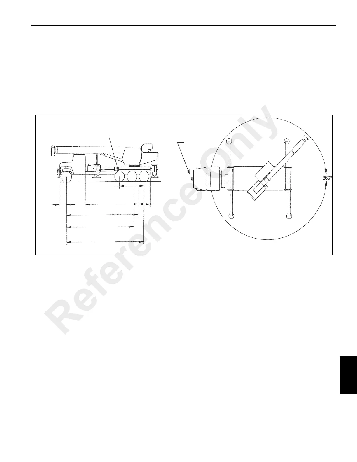
Configuration With Pusher Axle 58,000 lb GVWR, 103/127 ft Boom – NBT40 and NBT45
The mounting configuration (with pusher axle 58,000 lb
GVWR, 103/127 ft boom)
shown in Figure 9-3 is based on
an 85% stability factor.
The complete unit must be installed on the truck in
accordance with factory requirements, and a test performed
to determine actual stability and counterweight
requirements, since individual truck chassis vary.
NOTE: If bare truck weights are not met, counterweight will
be required.
A summary of mounting and truck requirements are listed as
follows:
• Working area 360°
• Gross Axle Weight Rating (GAWR), front 20,000 lb
• Gross Axle Weight Rating (GAWR), rear 40,000 lb
• Gross Vehicle Weight Rating 58,000 lb
• Gross Pusher Axle Rating 10,000 lb (min)
• Wheelbase (WB)258 in (Min. for 58,000 lb GVWR on
bridge law)
• Pusher Axle Location from Front Axle 180 in (Typ.)
• Frame Section Modulus (SM), front axle to end of (AF)
30 in
3
• After Frame (AF) 92 in (min)
• The minimum truck and pusher weight required for
stability (truck with pusher axle raised).
- 20,250 lb gross
- 9,475 lb front axle
- 10,275 rear axle
• Less Weight required if equipped with auxiliary hoist or
additional swinging counterweight.
• Additional options or heavier bare chassis weights will
require additional axles or a GVWR in excess of
58,000 lb; in some states special permits for overload
are required.
360° Full Capacity Working Area
FRONT
STABILIZER
92 MIN
28 MIN
97 MIN
180 CT
258 WB
282 APPROX.
C
L
ROTATION
283 MIN
(FOR 58,000 GVWR
ON BRIDGE LAW
PUSHER
FIGURE 9-3
7704
Reference Only

 Loading...


