SWING NBT40 SERVICE MANUAL
6-14 Published 8-01-2017 Control # 287-11
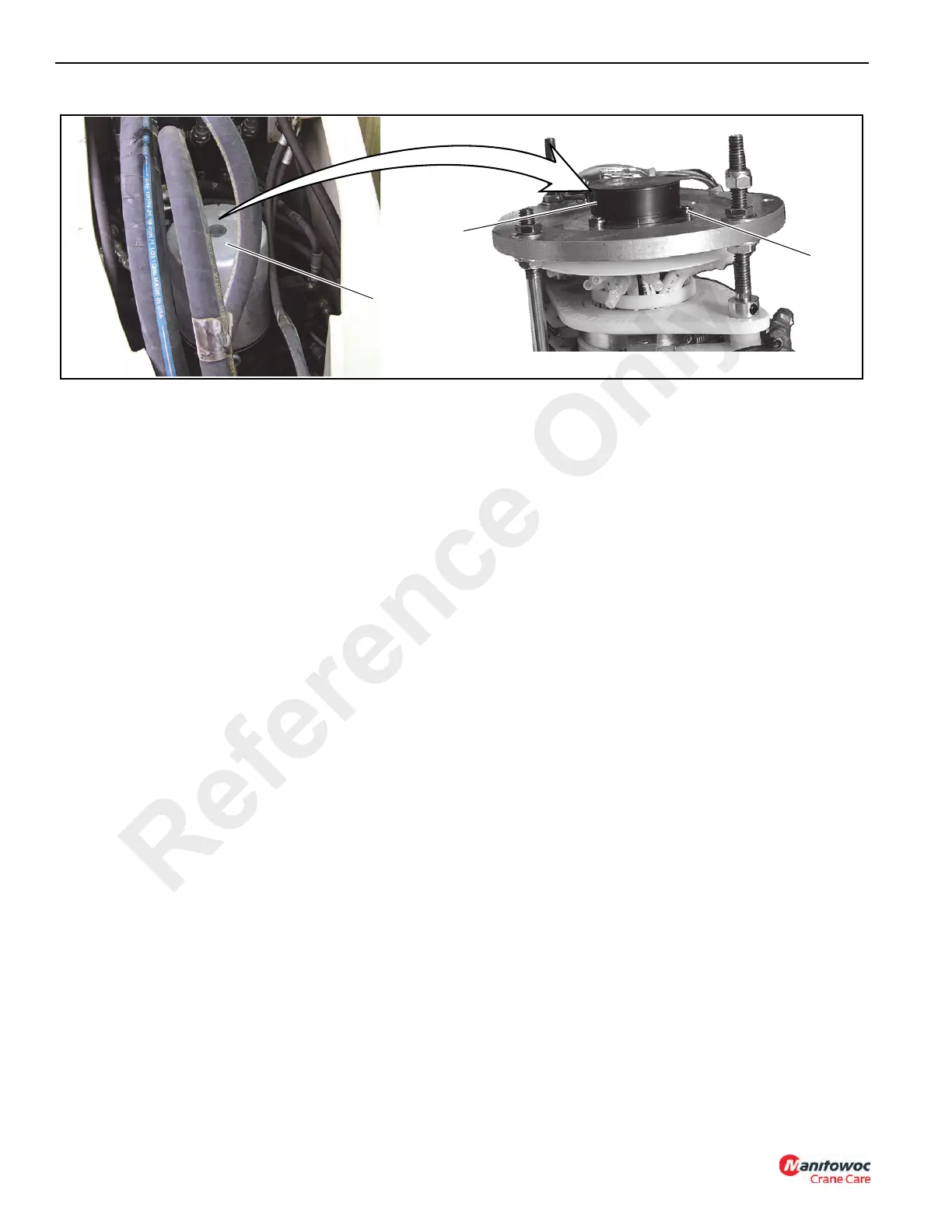
Slew Potentiometer Adjustment
The slew potentiometer is a component of the hydraulic and
electric swivel assembly which is mounted inside the
superstructure turret. The top part of the swivel assembly is the
electrical swivel section (1,Figure 6-11) and contains the slew
potentiometer (2, Figure 6-11).
1. Remove the cover from the electrical swivel section (1).
2. Using the cab controls to rotate the turret over the front
and set the swing brake.
3. Set the RCL console to read slewing angle as follows:
NOTE 1: Refer to the mentor QVGA Load Moment
Indicator Manual for detailed instructions.
a. Complete the RCL console setup according to the
crane’s current operating configuration.
b. Press limits LIM.
c. Press the OK button.
d. Toggle down to SLEW and press the ok button to
display the slew angle work area definition limits.
4. Remove the electrical swivel cover.
5. Release the swing brake. Swing the turret about 10° to
the right (clockwise). Slowly swing back to over the front
and set the swing brake.
NOTE: If the turret swings past the over the front position,
step 4 must be repeated.
6. Loosen the three screws (3,
Figure 6-11) that secure the
slew potentiometer to the mounting plate.
7. Rotate the body of the slew potentiometer (2,
Figure 6-11) until the slew angle indicates 0.6° ± 0.1°.
8. Tighten the three screws (3,
Figure 6-11) to secure the
slew potentiometer to the mounting plate. Install the
electrical swivel cover.
9. Disengage the swing brake and swing approximately
10° to the left (counterclockwise). Slowly swing back to
over the front and set the swing brake.
NOTE: If the turret swings past the house lock pin engaged
position, step 8 must be repeated.
10. If the angle indicated on the console does not exceed
± 1.0°, proceed to step 10. If the indicated angle
exceeds ± 1.0°, return to step 4.
11. Release the swing brake and swing approximately 10°
to the right (clockwise). Slowly swing back to over the
front and set the swing brake.
NOTE: If the Turret swings past the over the front position,
step 10 must be repeated.
12. If the angle indicated on the console does not exceed
± 1.0°, proceed to step 12. If the indicated angle
exceeds ± 1.0°, return to step 3.
13. Release the swing brake and swing approximately 10°
to the left (counterclockwise). Slowly swing back to over
the front and set the swing brake.
Testing
Activate the crane and check for proper function.
NOTE: If the turret does not turn freely after bearing and
pinion replacement, contact your local distributor.
SWING LOCK
The swing 360° lock holds the turret in place preventing any type
of movement in either a counterclockwise or clockwise direction.
This is a mechanical lock which is engaged and disengaged by
a cable assembly connected to the swing lock foot pedal located
in the operator’s cab.
Reference Only

 Loading...


