BOOM MAINTENANCE NBT40 SERVICE MANUAL
4-4 Published 8-01-2017 Control # 287-11
retract cables to 8.13 Nm (6 ft lb). Torque 1/2/3 extend
cable to 29.83 Nm (22 ft lb).
8. Cycle the boom through a complete extend and retract
cycle. Check that all cables are properly torqued and
that all sections retract completely.
9. Tightening until the retraction gap between the first and
second section and the retraction gap between the
second and the third are equal.
At this time the all extendable sections should extend and
retract equally and bottom out against the stops
simultaneously.
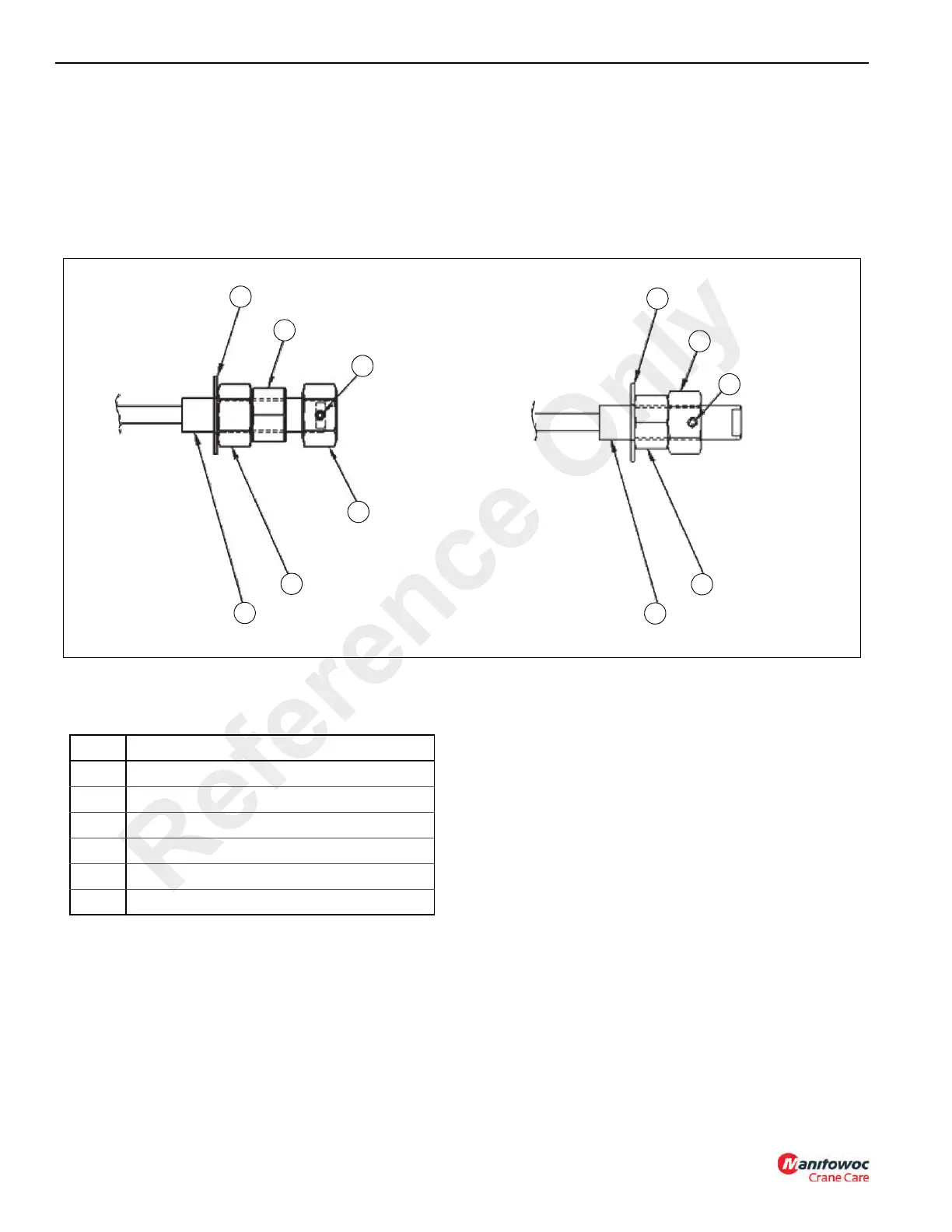
Cable Retention
Cable Retention Hardware
Nut configuration (see Figure 4-3) will be First Nut
(ADJUSTMENT) and Second Nut (TORQUED).
NOTE: (OPTION 2) method used ONLY when space
constraints prevent OPTION 1 usage.
When tightening/loosening the first (adjustment) nuts on
cables, secure cable using the wrench flats at the front of the
cable ends to prevent cable twist.
After the cable adjustment procedure is completed for the
entire boom assembly. The second (torqued) nut must be
installed on all retract and extend cables.
The second nut should be hand tightened until it comes in
contact with the back of the first nut.
Hold the first (adjustment) nut stationary and a torque
wrench to tighten the second (torqued) nut against the first
(adjustment) nut to the values indicated in TORQUE
VALUES for Second Nut:
Third (positive lock) nut installation is to be placed on each of
the extend cables. The retract cables do not require the third
(positive lock) nut.
The third nut should be hand tightened until the tapped hole
for the set screw is tangent to the end face of the wrench flat.
Install set screw into Third nut and tighten.
Install cable protectors to all threaded cable ends.
(OPTION 2) method used ONLY when space constraints
prevent OPTION 1 usage (see Figure 4-3).
8859-1
3
4
6
5
2
1
8859-2
3
4
5
2
1
OPTION 2
OPTION 1
FIGURE 4-3
Item Description
1 Threaded Cable End
2 Nut (Adjustment)
3 Nut (Positive Lock)
4 Setscrew
5
Washer
6 Nut (Torqued)
Reference Only

 Loading...


