NBT40 SERVICE MANUAL HYDRAULIC SYSTEM
National Crane Published 8-01-2017 Control # 287-11 2-19
4. Remove the bolts from the pump mounting flange and
slide the pump out of the PTO drive coupling.
Installation
1. Lubricate the splines on the pump and PTO drive shaft
coupling with heavy lithium grease.
2. Line up the splines on the PTO drive shaft coupling with
the pump drive shaft and slide the pump drive shaft into
the coupling.
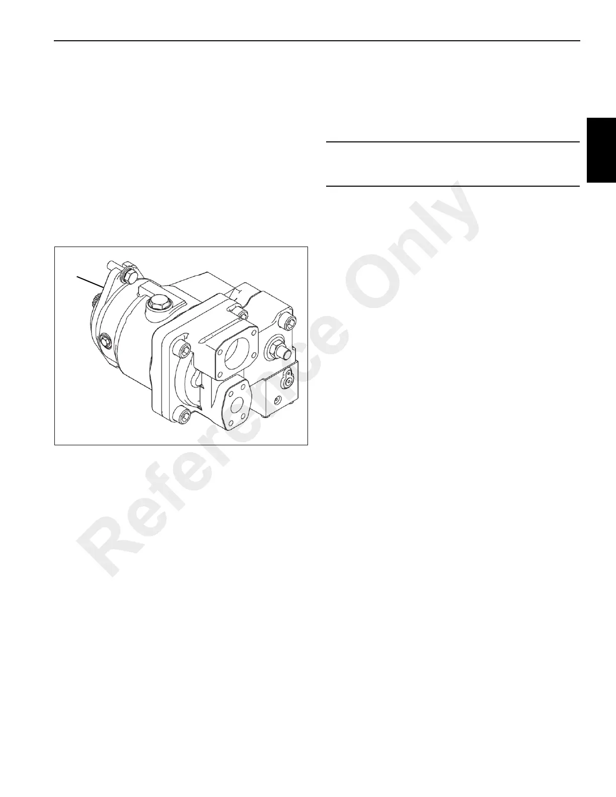
3. Bolt the pump (1, Figure 2-12) to the PTO with the pump
mounting flange.
4. Bolt the pump rear mounting bracket to the truck
mounting bracket.
5. Reconnect the hydraulic lines as per removal tags.
6. Start up the pump following procedures described under
Pump Start-up, page 2-19.
Pump Start-up
If the pump is removed for maintenance or replacement the
following startup procedure should be followed to prevent
damage to the pump or other components in the hydraulic
system.
1. Install pump on PTO following procedures described
under Installation, page 2-19.
2. Fill the reservoir with hydraulic oil.
3. Open the shut-off valve on the hydraulic line from the
reservoir to the pump.
4. Fill the pump housing with hydraulic fluid. Pour the oil
directly into the upper most case drain port.
5. Fill the inlet line from the pump to the reservoir with
hydraulic oil. Check the line for properly tightened
fittings, and be certain it is free of restrictions and air
leaks.
6. Inspect the case drain line for leaks and restrictions.
7. Install a gauge at the pump pressure gauge port on the
Main Directional Control Valve Manifold.
8. Start the engine and engage the PTO while monitoring
the pressure gauge. Do not operate any hydraulic
levers. If the pump does not build up pressure to 51 to
55 bar (750 to 800 psi), shut down the engine and take
corrective action.
9. Idle the engine for 2 to 3 minutes.
10. Operate the system under a light load for 5 to 10
minutes.
11. Check/adjust pump margin pressure; see Pump Margin
Pressure Setting, page 2-20.
12. Check/adjust maximum pump pressure; see Maximum
Pump Pressure Setting, page 2-20.
13. Remove pressure gauge. Check hydraulic oil level in
reservoir and fill if needed.
CAUTION
The supply line shut-off valve must be open to allow flow
to the pump to prevent pump damage.
Reference Only

 Loading...


