National Crane Published 8-01-2017 Control # 287-11 7-5
NBT40 SERVICE MANUAL OUTRIGGERS
22. Properly support the stabilizer cylinder from the bottom
with a floor jack or hoist and remove the holding valve
and o-rings.
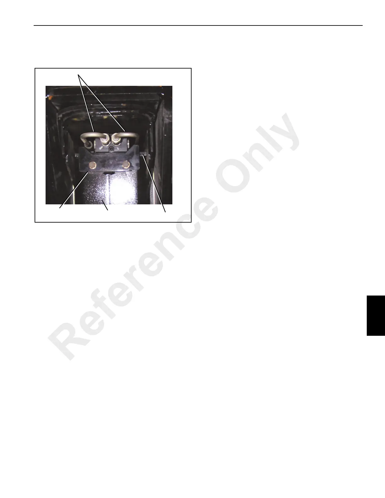
23. Remove the capscrews and lock plate from the stabilizer
tube.
24. With the cylinder supported, slide the retainer plate out
from under the cylinder butt plate.
25. Lower the cylinder out of stabilizer tube.
26. Remove the wear rings installed in grooves of lower
cylinder support legs.
Assembly
NOTE: When assembling the outriggers do the following:
• Always use the jam nuts and thread the first nut on
past the flat so adjustment can be made later.
• Do not use loctite on any threaded cable ends.
• Use loctite on all other bolts.
• Reassemble wear pads as per removal tags. If new
wear pads are used, readjust the pads and shims.
1. Install the stabilizer hydraulic tubes in the 2
ND
section
beam.
2. Install wear rings into stabilizer leg.
3. Insert the stabilizer cylinder into the stabilizer tube.
4. Slide the retainer plate under the stabilizer cylinder butt
end.
5. Install the lock plate and capscrews (Figure 7-5).
6. Install holding valve on stabilizer cylinder.
7. Install hydraulic fittings and tubes on the holding valve.
8. Install the wear pads and shims to 2
ND
section beam.
9. Place the 1
ST
section beam on adequate blocking and
slide the 2
ND
section into 1
ST
section until 2
ND
section
stops.
10. Install the side wear pads and shims between 2
ND
and
1
ST
section beams. Raise the 2
ND
section and install the
bottom front wear pads and shims.
11. Assemble proportioning cable sheave with shaft and
hose reels onto extend cylinder. Install the cables and
hoses and drape excess in area to avoid damage.
12. Insert extend cylinder into 1
ST
-2
ND
outrigger assembly.
Use caution to avoid pinching the cables and hoses.
13. Lift the cylinder up to allow cable anchor access and
install the fittings in the anchor plate assembly. Attach
stabilizer cylinder hoses.
14. Assemble the proportioning cable stop into cable anchor
and install the anchor in 2
ND
section beam.
15. Attach the fittings for the stabilizer cylinder hydraulic
tubes to the cable anchor.
16. Route the cables through sheave hole on bottom of 2
ND
beam section. Reeve cables around dual sheave and
install the sheave, shaft, and snap rings.
17. Lower cylinder trunnion into the pocket on the 1
ST
section beam.
18. With the 1
ST
-2
ND
section beam assembly on adequate
blocking, install the wear pads, and shims.
19. Attach the cables, fittings, and hoses to cylinder butt
plate. The cylinder length may need to be adjusted to
allow assembly.
20. Slide the 1
ST
-2
ND
section beam assembly into outrigger
box. Use caution not to damage the cables sliding in
under the 1
ST
section. The 1
ST
- 2
ND
beam assembly may
need to be lifted to install cable ends into the anchor
points in bottom of the outrigger box. Guide the cable
ends between outrigger box and the 1
ST
2
ND
assembly
back through the anchor points. Install anchor hex nuts
in previously marked positions.
21. Push the 1
ST
2
ND
beam assembly into the main outrigger
box until the butt plate of the extend cylinder reaches the
end of the outrigger box. Bolt the butt end of the extend
cylinder to the end of the outrigger box.
22. Reinstall the hydraulic lines and holding valve on the
extend cylinder.
23. Install the side and bottom wear pads and shims.
Hydraulic Tubes
Lock Plate
Retainer Plate
FIGURE 7-5
Stabilizer Tube
Reference Only

 Loading...


