NBT40 SERVICE MANUAL HYDRAULIC SYSTEM
National Crane Published 8-01-2017 Control # 287-11 2-7
which is determined by a pressure relief valve located on the
hydraulic pump.
Front Outrigger Manifold
The front outrigger manifold is located in the center of the
front manifold and controls the extend and retract circuits for
the front and rear outriggers. The manifold controls the
outrigger component selection for the front outrigger.
Rear Outrigger Control Manifold
The rear outrigger manifold is mounted in the center of the
rear outrigger. The rear outrigger manifold controls the
selection of the rear outrigger components.
Hydraulic Tank
The hydraulic tank (Figure 2-10) is located behind the cab
and has a capacity of 100 gallons to the full mark. The oil in
the hydraulic tank is used to supply the oil to the hydraulic
system when the hydraulic cylinders are extended.
Hydraulic Remote Controllers
The crane functions are controlled by hydraulic remote
controllers (HRC) on the armrest of the operators seat. The
controllers operate from a load sense pilot pressure which is
applied to the bonnets on each side of the valve spools to
shift the spool in the required direction.
HYDRAULIC VALVES
This section provides descriptive information for all the
hydraulic valves used on this crane. For a listing of all valves,
the circuit they are used in, and their physical location, refer
to the table below. Refer to (Figure 2-1) for control valve and
manifold locations. The description of each valve given here
is for the valve itself. For information on how each valve
functions in the individual circuits, refer to the description and
operation procedures of that circuit.
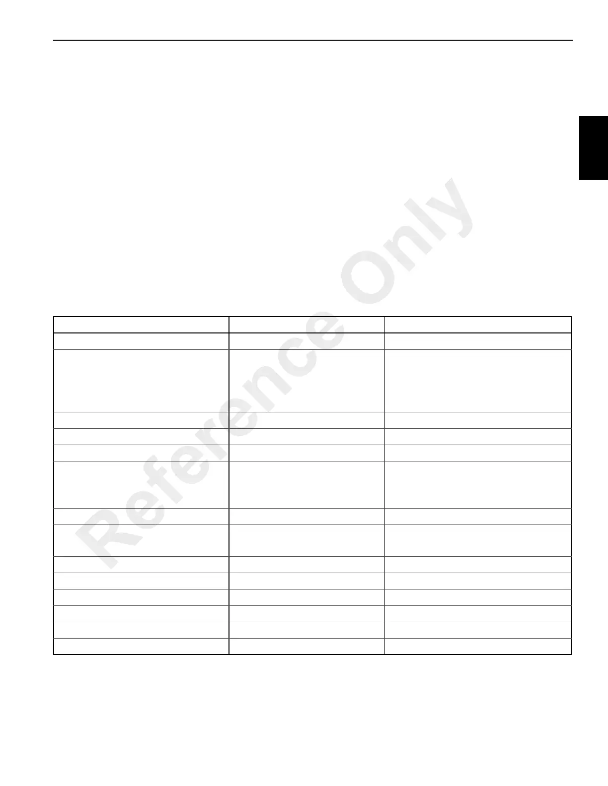
Hydraulic Valves
Valve Name Circuit Used In Physical Location
Main Control Valve Lift/Telescope(s)/Hoist(s) Inside the turret.
Hydraulic Remote Controllers (HRC)
Lift
Telescope
Main Hoist
Swing
Cab seat arm rests (2)
Swing Brake Pedal Valve Swing Crane Cab Floor
Swing Brake Manifold Swing Inside turret
Swing Speed Flow Control Valve Swing On swing motor
Holding Valves
Lift
Telescope
Outrigger
Port block on cylinder
Hoist Motor Control Valve Hoist Directional Control Valve
Bypass Valve Return circuit
One in parallel with oil cooler
One in parallel with oil filter
Front Outrigger Control Manifold Outrigger Front outrigger box
Rear Outrigger Control Manifold Outrigger Rear outrigger box
Pilot Operated Check Valve Outriggers Port block of each jack cylinder (4)
Front Center Stabilizer Relief Valve Outrigger Front center outrigger
Flow Control Valve Outriggers Front outrigger box.
Telescope Pedal Optional - with Aux Hoist Cab Floor
Reference Only

 Loading...


