SWING NBT40 SERVICE MANUAL
6-2 Published 8-01-2017 Control # 287-11
Swing Brake
Hydraulic power for the swing brake control is supplied by the
crane manifold and swing brake pedal valve. The hydraulic
power for the swing brake release is supplied by swing brake
release solenoid on the crane manifold. With the SWING
BRAKE selector switch positioned to ON, the swing brake
release valve blocks the regulated pressure to the brake release
port and spring pressure in the swing brake applies the brake.
When the SWING BRAKE selector switch is positioned to OFF,
the regulated pressure is directed from the pressure
reducing/sequence valve to the brake release port, overcoming
the brake spring pressure and releasing the swing brake.
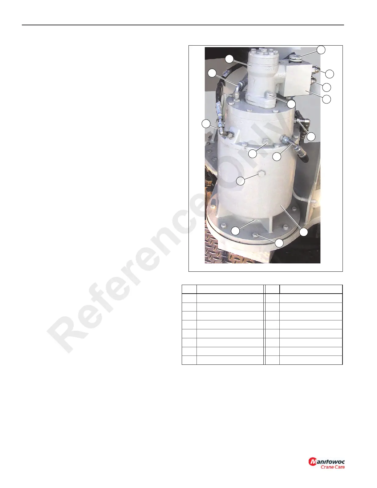
Swing Gear Box Assembly
Figure 6-1 Item List
FIGURE 6-1
4
1
2
3
5
6
7
8
10
9
11
13
4
12
7582-1
14
15
Item Description Item Description
1 Motor 9 Fill
2 Adjustable Speed Valve 10 Drain
3 Hose Brake Coolant Out 11 Gear Box
4 Control Valve 12 Control Clockwise
5 Hose Service Brake Apply 13 Control Counter-clockwise
6 Breather 14 Screw & Flatwasher, 3/4”
7 Hose Brake Coolant In 15 Screw & Lockwasher, 1/2”
8 Hose Parking Brake Release
Reference Only

 Loading...


