A
B
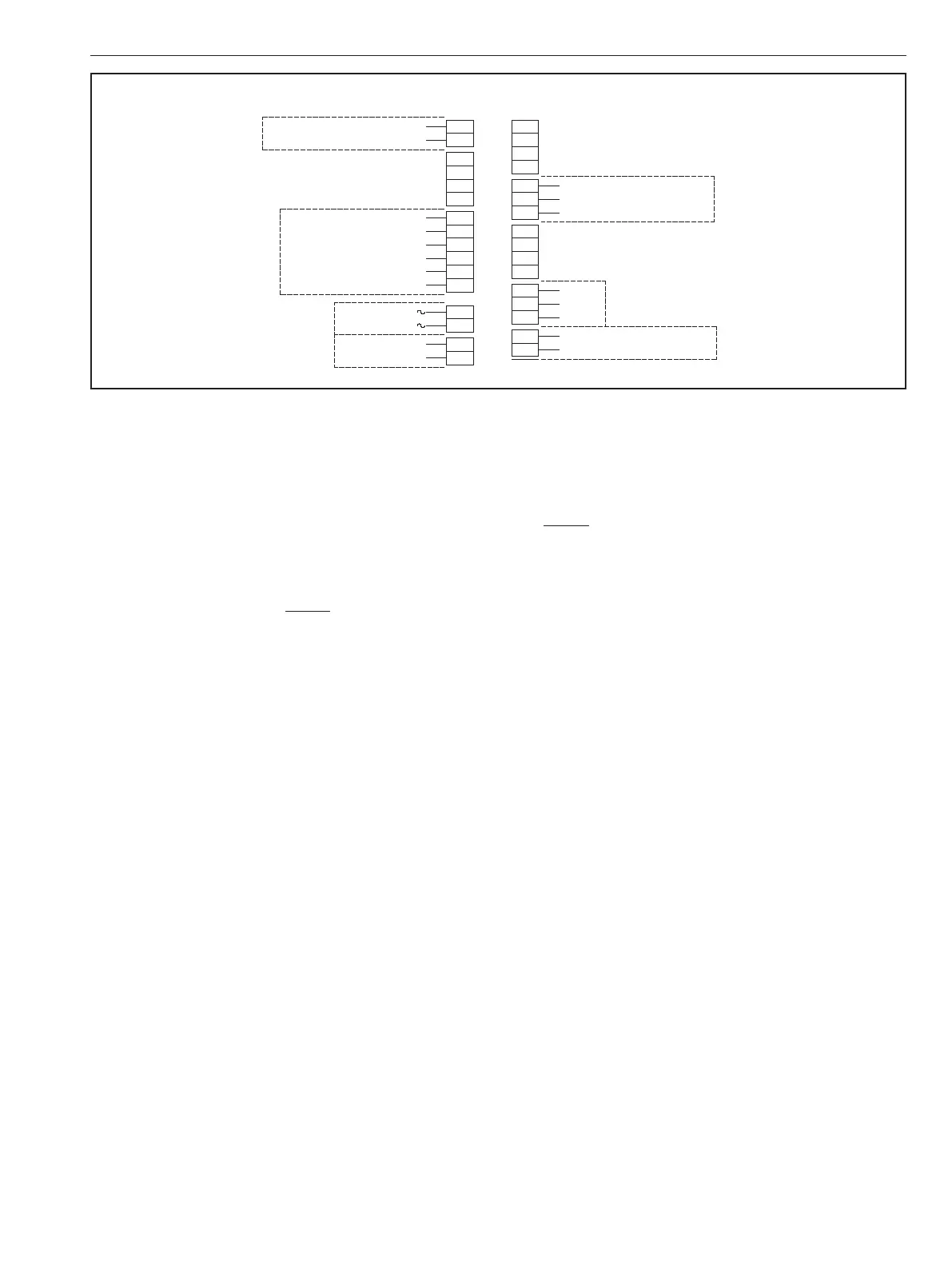
Hot / L1
115/230VAC
Neut. / L2
C
D
E
F
G
H
I
J
K
L
NO
NC
CW S witch 1 C OM
NO
NC
CCW Switch 2 C OM
mA / VDC+
Opt. External +24VDC F eedback
+
-
Wiper R esistive C ontrol
+
4-20mA or 0-10VDC Analog C ontrol
-
1
2
3
4
5
6
7
8
9
10
11
12
13
14
15
16
mA / VDC-
17
18
19
20
24VAC
+
12/24VDC
-
Low Voltage Power
Auxiliary Switches
High V oltage P ower
Position C ontrol
A
B
Hot / L1
115/230VAC
Neut. / L2
C
D
E
F
Hot / L1 CW
Hot / L1 MID
Hot / L1 CCW
Neut. / L2 C OM
G
H
I
J
K
L
NO
NC
CW S witch 1 C OM
NO
NC
CCW Switch 2 C OM
mA / VDC+
Opt. External +24VDC F eedback
1
2
3
4
5
6
7
8
9
10
11
12
13
14
15
16
mA / VDC-
17
18
19
20
24VAC
+
12/24VDC
-
Low Voltage Power
Auxiliary Switches
P os. / Hot C W
P os. / Hot MID
P os. / Hot CCW
115/230VAC
High V oltage P ower
On/O Control
High V oltage
On / O Control
Low Volta ge
On / O C ontrol
12/24VDC
or 24VAC
Neg. / Com. C OM
Positioning Control Wiring
Figure 12
7.3 Set Up and Calibration
7.3.1 Initial Set Up
1. Remove actuator cover. Remove the override shaft
from the actuator cover bushing; if the actuator is
equipped with a handwheel, remove the handwheel
before removing the top piece of the “two-piece” shaft
from the cover bushing. NOTE: Use caution to prevent
damage to machined flange surface of cover casting;
see cover replacement for additional information.
2. Select LIMIT type “Smart” by sliding the [Smart/Cam]
switch up to select Smart. Selecting Smart will enable
other features on the board such as Position Feedback.
3. Select Control Method “Analog” or “Resistive” by
turning the selection potentiometer with a small flat
blade screwdriver.
7.3.2 Potentiometer Calibration
Field installation of the Universal Control Board option
or replacement of the position tracking potentiometer
requires calibration of the position tracking potentiometer
prior to setting positions and values for ZERO, MID and SPAN.
Universal Control Board options installed at the factory are
fully calibrated at the factory and should not require further
calibration. To confirm proper potentiometer calibration:
1. Turn the Mode Selector Dial to [CAL] and press [ENTER]
for 2 seconds.
2. Using the CW pushbutton, drive the actuator to the
full clockwise position. - If the [CAL] LED is flashing,
potentiometer calibration is required; proceed to step
3 below. - If the [CAL] LED remains on, calibration is
not required; proceed to Setting ZERO, MID and SPAN
Positions section below.
3. Loosen the set screw in the gear with a 1/16” hex
wrench.
4. Rotate the gear until the LED remains on constantly;
hold the gear in place and tighten the set screw. Ensure
that the LED remains on after the set screw is tightened.
NOTE: The LED assists the user in locating the proper
calibration window; it will flash faster as you approach
the calibration window and slower as you move away
from it.
5. Press the [ENTER] button to save the potentiometer
setting.
7.3.3 Setting ZERO, MID, and SPAN Positions
Once (feedback potentiometer) calibration has been
confirmed, set the desired “end of travel” positions. Make
certain that the limit switch cams are set to operate the
switches beyond the desired range for the ZERO and SPAN
positions. ZERO and SPAN may be set at any position
between 0° and 94° of travel (0° and 184° with “U4”, “UL4” or
“UL5” option; or 0° and 274° with “U6”, “UL6” or “UL7” option).
Set ZERO (typically CW):
1. Turn the Mode Selector Dial to [ZERO] and press
[ENTER] for 2 seconds. The [ZERO] LED will begin to
flash.
2. Drive the actuator to desired clockwise position using
the CW or CCW push button. If the “STALL” LED
begins to flash; check to see if the limit switch cam is
preventing actuator from reaching desired ZERO end-
of-travel (the “Switch Trip” LED will be illuminated).
If necessary back the cam off so that it will trip the
switch slightly beyond the desired end-of-travel and
the “Switch Trip” LED will go out.
3. Apply the desired Analog Signal that will correspond
with the Zero position (ie 4mA).
4. Press the [ENTER] button to save the ZERO setting.
IMO 6/18
IMO-I4900 EN 11

 Loading...