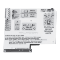
17.1 ADC-SERIES UNIVERSAL CONTROL BOARD
Table 3 Control Board Specifications
Input Impedance
(Analog Control)
Voltage Input: 35K ohms
Current Input: 200 ohms
Analog Control Signal May be either 4-20mA or 0-10VDC (selectable via on-board slide swithch)
Fully compatible with ISA-S50. 1 as a type 4, class L, power isolated device.
Input minus (-) and transmit minus (-) are tied together and isolated from power and earth ground.
Resistive Control Signal Board will accept a resistance control signal as low as 0-100 ohms and as high as 0-10K ohms.
Position Out Signal May be either 4-20mA or 0-10VDC (selectable via on-board slide switch)
Minimum resistive load for voltage output: 1K ohm
Maximum resistive load for current output: 500 ohm
Stall Protection If the actuator cannot achieve the position commanded by the control signal, this feature will
remove all power to the motor after 5 seconds. The actuator will not restore power to the motor
until the control signal commands the actuator to drive in the opposite direction.
Power Loss Position In the event of a loss of main power, user can choose either the Zero position or the Span, or Mid
position, via selector pot, as the power loss “Park” position.
Power Fail Park or
Battery Cycle
In the event of a loss of main power, user can choose either to drive the
actuator immediately to the “Park” Power Loss Position or continue to cycle (if control signal is avail-
able) until low battery level is detected before driving to the “Park” position.
Control Fail Position
In the event of a loss of control signal (with power still supplied), user can choose either the Zero,
Span or the Last position via slide switch
NOTE: If the the minimum control signal = 0, the fail position must be Last
Position Potentiometer 360° Rotation, 0 ohms to 1k ohms.
Local Supervisory Control User can select manual (MAN) to override control signal and drive actuator by pushing the CW or
CCW buttons. Actuator may be manually positioned to any location between the existing Zero and
Span settings. For additional range, reset the ZERO and Span locations.
Split Range Control Actuator will accept split range control signal (i.e. 4-12mA or 12-20mA; 0-5V or 5-10V) with no
wiring changes.
Reverse Acting With no wiring changes required, the actuator may be calibrated to drive clockwise upon an
increasing control signal, and counter-clockwise upon a decreasing signal.
Dead Band The amount of change in control signal that the actuator will ignore before the output shaft begins
to move. Adjustable from 1% to 3%.
IMO 6/18
IMO-I4900 EN 21

 Loading...