Set MID: (if applicable)
1. Turn the Mode Selector Dial to [MID] and press [ENTER]
for 2 seconds. The [MID] LED will begin to flash.
2. Drive the actuator to the desired MID or “THIRD”
position using the CW or CCW push button.
3. Press the [ENTER] button to save the MID setting.
Set SPAN (typically CCW):
1. Turn the Mode Selector Dial to [SPAN] and press
[ENTER] for 2 seconds. The [SPAN] LED will begin to
flash.
2. Drive the actuator to desired counterclockwise position
using the CW or CCW push button. If the “STALL” LED
begins to flash; check to see if the limit switch cam is
preventing actuator from reaching desired SPAN end-
of-travel (the “Switch Trip” LED will be illuminated).
If necessary, back the cam off so that it will trip the
switch slightly beyond the desired end-of-travel and
the “Switch Trip” LED will go out.
3. Apply the desired Analog Signal that will correspond
with the Span position (ie 20mA).
4. Press the [ENTER] button to save the SPAN setting.
7.3.4 Verify End-Of-Travel Settings:
1. Turn the Mode Selector Dial to [RUN].
2. Apply various control signals to verify operation.
3. Verify that the “Switch Trip” LED is not illuminated at
either the ZERO or SPAN positions (if it is, “back” the
respective end-of-travel cam “o” of the respective
limit switch).
4. Replace actuator cover.
7.3.5 Proper Actuator Cover Replacement
NOTE: For actuators including hazardous location certi-
cation. Prior to installing cover, inspect machined ange
surfaces for any damage, scratches, or dents. Damage,
scratches, or dents that will not t completely in a circle
having a diameter of 1/64” will void hazardous location certi-
cations. If such imperfections are present the damaged
enclosure part(s) must be replaced. Consult the factory for
replacement parts.
1. Remove the override shaft from the actuator cover
bushing; if the actuator is equipped with a handwheel,
remove the handwheel before removing the top piece
of the “two-piece” shaft from the cover bushing.
2. Install the override shaft on the square motor shaft; if
the actuator is equipped with a handwheel, install the
bottom piece of the “two-piece” shaft on the motor
shaft and then install the top piece of the shaft onto
the bottom piece of the shaft.
3. Align cover so that the override shaft will pass through
the override bushing and carefully push it down so
that the cover flange contacts the base flange.
4. Once the cover is properly seated, tighten the screws
to secure the cover; a cross pattern is recommended
for uniform distribution of load.
5. If the position indicator is not seated to the output/
cam shaft, turn until it drops into place in order to
ensure accurate visual position indication.
7.4 Deadband Adjustment
Dead Band is the window of control signal change which
the actuator will ignore. The sensitivity of the actuator to
respond to changes in the control signal is adjustable.
Minimum Dead Band (1%) allows the actuator to respond
to small control signal changes. Maximum Dead Band (3%)
allows the actuator to ignore small control signal changes
(such as noise on the control signal).
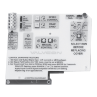
7.5 Signal Fail Options
In the event that the control signal to the actuator is lost
and external power is still applied, the Signal Fail position
selector switch on the Universal Control Board provides
options for the actuator to drive to the Zero (minimum
signal) position, the Span (maximum signal) position, or to
remain at its “Last” (current) position. NOTE: If you use a
0- 10VDC control signal, the actuator cannot differentiate
between a 0VDC signal and an actual loss of signal;
therefore, it will drive to the “Zero” position regardless of
the switch setting.
IMO 6/18
12 IMO-I4900 EN

 Loading...