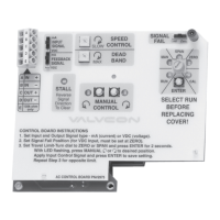
Figure 22
Re-install the board overlay.
Figure 23
The actuator is now ready to be re-calibrated and set up for
your application. Please refer to sections 4 through 9 of this
manual for calibration and set up procedures and option
settings.
13. REASSEMBLY
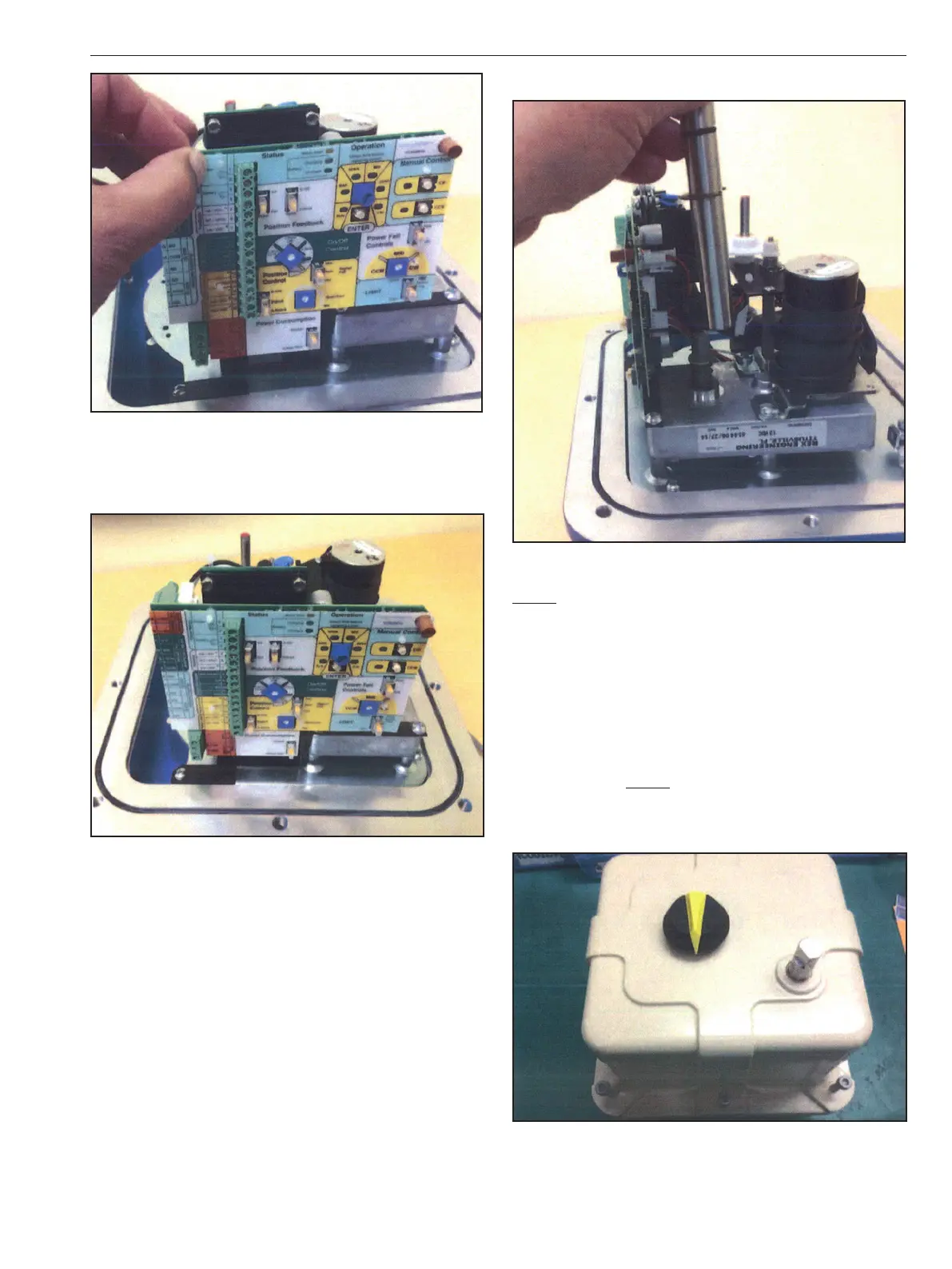
Figure 24
NOTE: For actuators including hazardous location certica-
tion. Prior to installing cover, inspect machined ange surfaces
for any damage, scratches, or dents. Damage, scratches, or
dents that will not t completely in a circle having a diam-
eter of 1/64” will void hazardous location certications. If such
imperfections are present the damaged enclosure part(s)
must be replaced. Consult the factory for replacement parts.
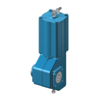
Once the actuator is calibrated and set for the application,
verify operation. Locate the over-ride shaft (remove from
cover bushing) and install it on the square shaft of the
motor/gearbox. (NOTE: If the actuator is equipped with a
handwheel, install the bottom part of the two-piece shaft on
the motor/gearbox shaft, and then install the top part of the
two-piece shaft onto the bottom shaft)
Figure 26
Use the override shaft as a guide the align and re-install the
cover onto the base and secure it with the screws that were
previously removed.
IMO 6/18
IMO-I4900 EN 17

 Loading...