are inside of the electronically saved travel stop positions,
or some other increase in the torque load on the actuator.
11 - Battery Charging* – A continuous yellow LED indicates
that the battery charging circuit is active to either charge or
maintain the voltage on the Battery.
12 - Battery Charged* – A continuous green LED indicates
that the battery is fully charged. A flashing green LED
indicates the actuator is running on battery power. This LED
will turn off in Energy Save mode.
* NOTE: Battery Charging and Battery Charged LEDs may be lit at the
same time depending on the battery charge state.
13 - Switch Trip – A continuous red LED indicates that one of the
end-of-travel limit switches has been “tripped” by the respective
cam; this LED is intended to aid initial actuator set-up.
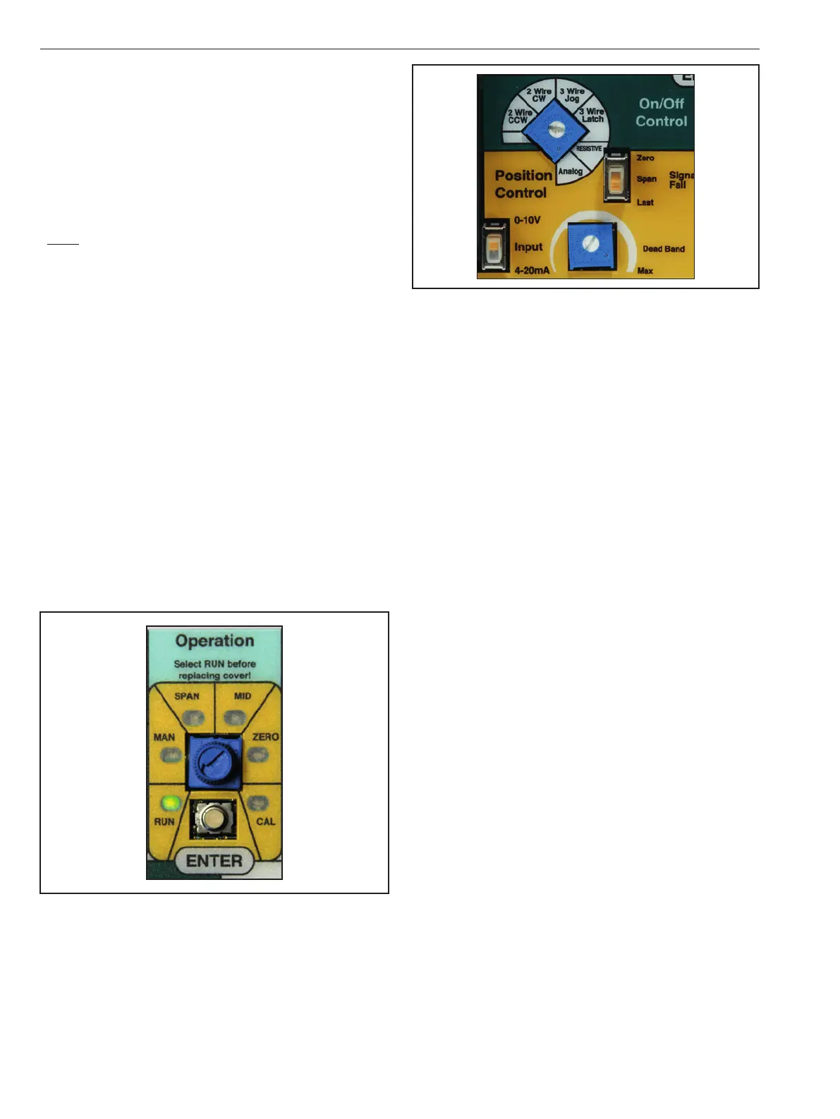
4.2 Operation Mode Selector Pot
The Universal Control Board is equipped with an Operation
Mode Selector Pot which allows the user to select the 6
modes of operation during calibration and set-up. LED
indicators around the knob correspond to each of the
modes; RUN, Manual (MAN), SPAN, MID, ZERO and Calibrate
(CAL). When the Universal Control Board mode dial is set to
any mode, the corresponding LED turns on, indicating the
mode is selected.
In MAN (Manual) and CAL mode the unit will ignore any
external control signals and respond only to the on-board
push buttons (it should be noted that if the unit is equipped
with an optional back-up battery and loss of power should
occur while in MAN and CAL mode, the unit will drive to the
selected “Power Fail” position).
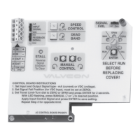
4.3 Control Mode Selector Pot
The Universal Control Board is equipped with a Control
Mode Selector Pot which enables the user to select
between various “On/O Control” and “Position Control”
modes.
Figure 5
4.4 Travel Limit Cam and Switch Operation
With the Universal Control Board installed, the travel limit
stops are set electronically as the Zero and Span position.
Two limit switches operated by the cams on the output
shaft are safety stops. Their intended function is to prevent
damage in the event of a failure of the electronic limits.
Therefore: Each cam must be set to operate the switch
slightly outside of the electronic Zero and Span position
range. Failure to set the cams properly may cause the
actuator to stall when it cannot reach the commanded
and electronically set end of travel position. The bottom
limit switch determines clockwise safety stop position.
The next limit switch, up from the bottom, determines the
counterclockwise safety stop position. Auxiliary switches
and the corresponding cams will be the third and fourth up
from the bottom.
Travel limits, also referred to as “end of travel stops”, are
the precise positions to which the actuator will drive. For
“2 Wire” or “3 Wire” On/Off operation, travel limits are set
at the full clockwise (CW) and full counter-clockwise (CCW)
ends of travel.
To simplify the process of setting the precise travel limit
positions, the ADC-Series provides two On/Off travel limit
types. CW, CCW and MID may be set electronically via the
“Smart” limit utility or CW and CCW may be set mechanically
by selecting the “Cam” limit type.
4.4.1 Smart Limit
When “Smart” is selected as the limit type, the microprocessor
stores the exact positions where the actuator will stop at
each end of travel or mid position. Setting the “Smart”
limit positions for the ZERO (typically CW), MID, and SPAN
(typically CCW) positions is done with the selector knob
and [ENTER] button in the Operation field of the Universal
Control board. To use the Smart limit features, the Feedback
Potentiometer must be installed, connected and calibrated
and the travel stop cams must be set to trip the switches
slightly beyond the desired “electronic” stop positions for
ZERO and SPAN. The end-of-travel limits on ADC actuators
can be entered and saved between 0° and 270° of travel.
For 180° and 270° rotation alternate potentiometer gearing
is required (refer to option code). For “Three-Position”
operation, limits must be entered and saved using the
“Smart” Limit!
Figure 4
IMO 6/18
6 IMO-I4900 EN

 Loading...