WARNING
IF USING 24VAC TO POWER THE ACTUATOR, A DEDICATED POWER
SUPPLY OR ISOLATION TRANSFORMER MUST BE USED.
5.3 12VDC or 24VDC Power Wiring
If using 12VDC or 24VDC as the MAIN Input Power: 12/24
VDC must be supplied constantly to the Universal Control
Board as follows:
- Terminal 19 (DC POS)
- Terminal 20 (DC NEG)
6. ON/OFF CONTROL See Figure 5
6.1 The three methods of On/Off Control:
The On/Off Control mode allows the actuator to drive in a
desired direction in response to an application of voltage to
the desired inputs. The different modes are as follows:
6.1.1 “2 Wire CW”
The actuator will default to the CCW position when main
actuator power is present; the actuator will drive CW when
the “CW” control power is energized.
6.1.2 “2 Wire CCW”
The actuator will default to the CW position when main
actuator power is present; the actuator will drive CCW when
the “CCW” control power is energized.
6.1.3 “3 Wire Jogging” Operation
(Open/Stop Close)
The actuator will drive CCW when the “CCW” control power
is energized and drive CW when the “CW” control power
is energized; if control power is removed mid-travel, the
actuator will stop in position. The actuator will drive to the
programmed “MID” position when the “MID” control power
is energized. The “MID” position is optional and can be set
anywhere inside of the CW and CCW end-of-travel positions
settings to provide a Three-Position “Center-Off” position,
or a “Dribble Feed” position.
6.1.4 “3 Wire Latching” Operation
The actuator will “latch” and drive CCW when the “CCW”
control power is momentarily energized. The actuator
will “latch” and drive CW when the “CW” control power is
momentarily energized. After energizing the control power
can be removed, as the direction of travel is “latched” in and
the unit will continue to drive to the respective travel limit.
The actuator will “latch” and drive to the programmed “MID”
position when the “MID” control power is momentarily
energized. The “MID” position is optional and can be set
anywhere inside of the CW and CCW end-of-travel positions
settings to provide a Three-Position “Center-Off” position,
or a “Dribble Feed” position.
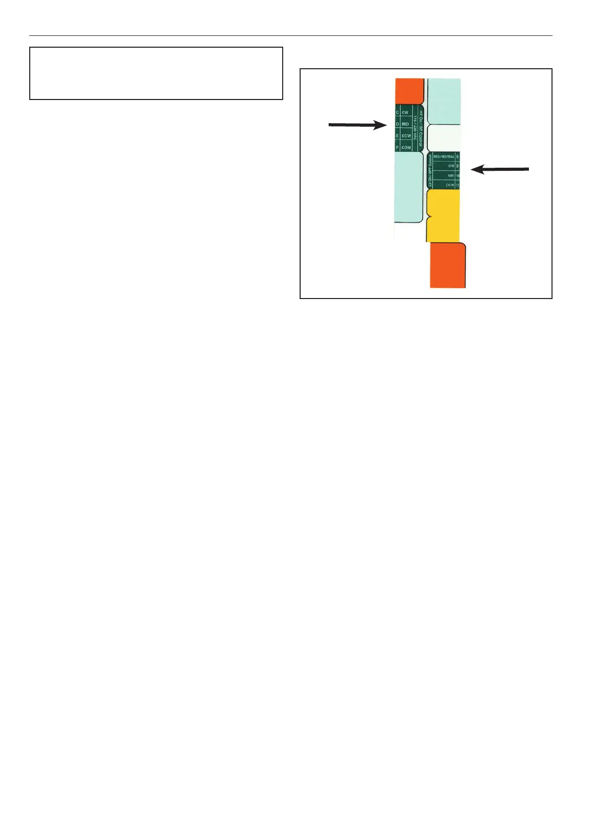
6.2 On/Off Control Signal Wiring
Figure 10
6.2.1 High Voltage:
To control the actuator with a high voltage signal (115VAC
or 230VAC): Connect AC L2/NEUT to terminal F on the
Universal Control Board. Energize AC L1/HOT at terminal
C on the Universal Control Board to drive the actuator
clockwise (CW). Energize AC L1/HOT at terminal D on the
Universal Control Board to drive the actuator to the “MID”
position. Energize AC L1/HOT at terminal E on the Universal
Control Board to drive the actuator counter-clockwise
(CCW).
6.2.2 Low Voltage:
To control the actuator with a low voltage signal (12VDC,
24VDC or 24VAC): Connect 12/24DC NEG or 24AC NEUT to
terminal 8 on the Universal Control Board. Energize DC POS
or 24AC HOT at terminal 9 on the Universal Control Board to
drive the actuator clockwise (CW). Energize DC POS or 24AC
HOT at terminal 10 on the Universal Control Board to drive
the actuator to the “MID” position. Energize DC POS or 24AC
HOT at terminal 11 on the Universal Control Board to drive
the actuator clockwise (CCW).
IMO 6/18
8 IMO-I4900 EN

 Loading...