EasyManua.ls Logo

Metso Valvcon ADC Series User Manual

Metso Valvcon ADC Series
24 pages
To Next Page IconTo Next Page
To Previous Page IconTo Previous Page
Page #13 background image
8. POSITION FEEDBACK AND STATUS
INDICATORS
8.1 Position Feedback
The Position Feedback provides an analog indication of the
actuator output position scaled between the configured
Zero and Span positions.
Figure 13
8.1.1 4-20mA
The 4-20mA Feedback can be powered either internally (by
the actuator) or externally (by the loop).
If the Position Feedback will be powered internally, connect
as follows: NEG to terminal 5; POS to terminal 7.
If the Position Feedback will be powered externally, it is
extremely important to terminate the customer supplied
+24VDC to the correct terminal on the Universal Control
Board. The Position Feedback switches are also important.
The Power Switch should be down in the “Ext” position
and the Signal Switch should be down into the “4-20mA”
position. (See Figure 14 for wiring options).
Figure 14
The 4-20mA Feedback circuit will power down if no
impedance is measured on the output terminals in both
Normal and Energy Save Mode operation. This is to stop any
unnecessary power drain while the 4-20mA feedback circuit
is not connected. Keep the metering circuit connected to
ensure that the feedback will be available as needed. If the
actuator position changes and there is a metering circuit
connected, then the feedback circuit will resume operation
and track the position.
8.1.2 0-10VDC
The 0-10V Feedback can only be used with internally (by
the actuator) supplied power.
The Position Feedback switches are also important. The
Power Switch should be up into the “Int” position and the
Signal Switch should be up into the “0-10V position.
8.2 Status Indicators
8.2.1 Auxiliary Switches
Two auxiliary limit switches will provide position indication
for customer use. The switches are dry contacts that can
be used to operate other devices. Switches are single pole,
double throw; rated for 11A, 1/2HP, 250VAC, CSA certified.
8.2.2 Power Status Relay
The Power Status Relay is “high” if external voltage (12-
24VDC, 24VAC power inputs to the board and the output
from the Switching Power Supply to the board) is greater
than 12.5V. The relay is “low” if external voltage drops
below 10.5V and will alternate between “high” and “low” if
the motor is stalled.
8.2.3 Battery Status Relay
The Battery Status Relay is “high” if battery is present (Vbat
>= 6V) and fully charged (Charger current is <10mA); if
the relay switches to “low” the back-up battery should be
checked/replaced. NOTE: After a loss of external power,
the Battery Status Relay may show “low” for a period of time
while the battery is charging.
9. POWER MANAGEMENT
9.1 Battery
With the optional battery backup (included with options
UL2, UL3, UL4, UL5, UL6 & UL7), the actuator will sense the
loss of main input power to the Universal Control Board
and immediately switch to internal battery power. When
line power returns, the actuator will automatically resume
normal operation.
The battery charging voltage has been designed for
optimum battery performance. When the charging circuit
is active (even when topping off charge or in sleep mode),
the yellow Charging LED will light. After reaching full
charge, the green Charged LED will light. *Fully charged,
the battery voltage will reach approximately 13.6 volts.
IMO 6/18
IMO-I4900 EN 13

Table of Contents

Question and Answer IconNeed help?

Do you have a question about the Metso Valvcon ADC Series and is the answer not in the manual?

Metso Valvcon ADC Series Specifications

General IconGeneral
Input Signal4-20 mA
Supply Voltage24 VDC
TypeController
SeriesADC
Communication ProtocolHART

Summary

General Information

Scope of the Manual

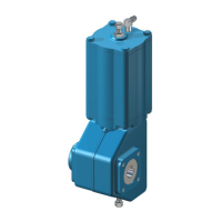
Provides essential information for the installation, operation, and maintenance of the Valvcon ADC-Series electric actuator.

Actuator Markings

Details the identification label attached to the actuator base casting, listing key specifications and certifications.

Safety Precautions

Highlights critical warnings regarding actuator performance and electrical limitations to prevent damage or injury.

Transportation and Storage

General Installation Information

Description of ADC-Series Universal Control Actuators

Explains the ADC-Series actuators, their enclosure types, torque ranges, and optional battery back-up features.

Universal Control Board P/N VCB00010

Details the Universal Control Board, its capabilities, and its role in ADC-Series actuator operation.

General Installation Information

Interface

Describes the interface of the Universal Control Board, including LED indicators for different operational modes.

General Installation Information

Operation Mode Selector Pot

Explains the function of the Operation Mode Selector Pot and its corresponding LED indicators.

Control Mode Selector Pot

Details the Control Mode Selector Pot for choosing between On/Off and Position Control modes.

Travel Limit Cam and Switch Operation

Describes how limit cams and switches function as safety stops for electronic travel limits.

General Installation Information

Smart Limit

Explains the 'Smart Limit' feature for electronically setting precise end-of-travel positions for actuators.

General Installation Information

Cam Limit

Details the 'Cam Limit' type, using mechanical limit switches operated by cams for setting travel limits.

Built-In Heater/Thermostat Feature

Describes the built-in heater/thermostat option for controlling operation in low-temperature or high-humidity environments.

Torque Limit

Explains the actuator's torque limit feature and the location of the setting potentiometer.

Main Actuator Power

115VAC or 230VAC Power Wiring

Provides wiring instructions for connecting 115VAC or 230VAC main input power to the Universal Control Board.

Main Actuator Power

24VAC Power Wiring

Details the wiring requirements for connecting 24VAC main input power to the Universal Control Board.

12VDC or 24VDC Power Wiring

Explains how to wire 12VDC or 24VDC main input power to the Universal Control Board.

On/Off Control

The three methods of On/Off Control

Describes the three methods of On/Off control: 2 Wire CW, 2 Wire CCW, and 3 Wire Jogging/Latching.

On/Off Control Signal Wiring

Provides wiring diagrams and instructions for high and low voltage On/Off control signals.

Set Up and Calibration

Details the procedures for setting up and calibrating the actuator for On/Off control modes.

On/Off Control

Initial Set Up

Step-by-step guide for initial setup, including cover removal and selecting limit types and control methods.

Potentiometer Calibration

Instructions for calibrating the position tracking potentiometer for accurate end-of-travel settings.

Setting ZERO, MID and SPAN Positions

Procedure for setting the desired ZERO, MID, and SPAN end-of-travel positions for the actuator.

On/Off Control

Verify End-Of-Travel Settings

Guidance on verifying the set end-of-travel positions and proper actuator cover replacement.

Proper Actuator Cover Replacement

Instructions for correctly reinstalling the actuator cover, emphasizing care for hazardous location certifications.

Position Control

The three methods of Position Control

Explains position control modes: 4-20mA Current Analog, 0-10VDC Voltage Analog, and Resistive Control.

Position Control Signal Wiring

Provides wiring details for analog and resistive position control signals to the Universal Control Board.

Position Control

Set Up and Calibration

Covers setup and calibration for position control, including initial setup and potentiometer calibration.

Initial Set Up

Step-by-step process for initial setup of the actuator for position control applications.

Potentiometer Calibration

Instructions for calibrating the position tracking potentiometer for position control settings.

Setting ZERO, MID, and SPAN Positions

Procedure to set ZERO, MID, and SPAN positions for position control, including signal application.

Position Control

Verify End-Of-Travel Settings

Guidance on verifying end-of-travel settings for position control and proper cover replacement.

Proper Actuator Cover Replacement

Detailed steps for replacing the actuator cover, with emphasis on maintaining certifications.

Deadband Adjustment

Explains how to adjust the deadband to control actuator sensitivity to signal changes.

Signal Fail Options

Details the options for actuator behavior upon loss of control signal, including Zero, Span, or Last position.

Position Feedback and Status Indicators

Position Feedback

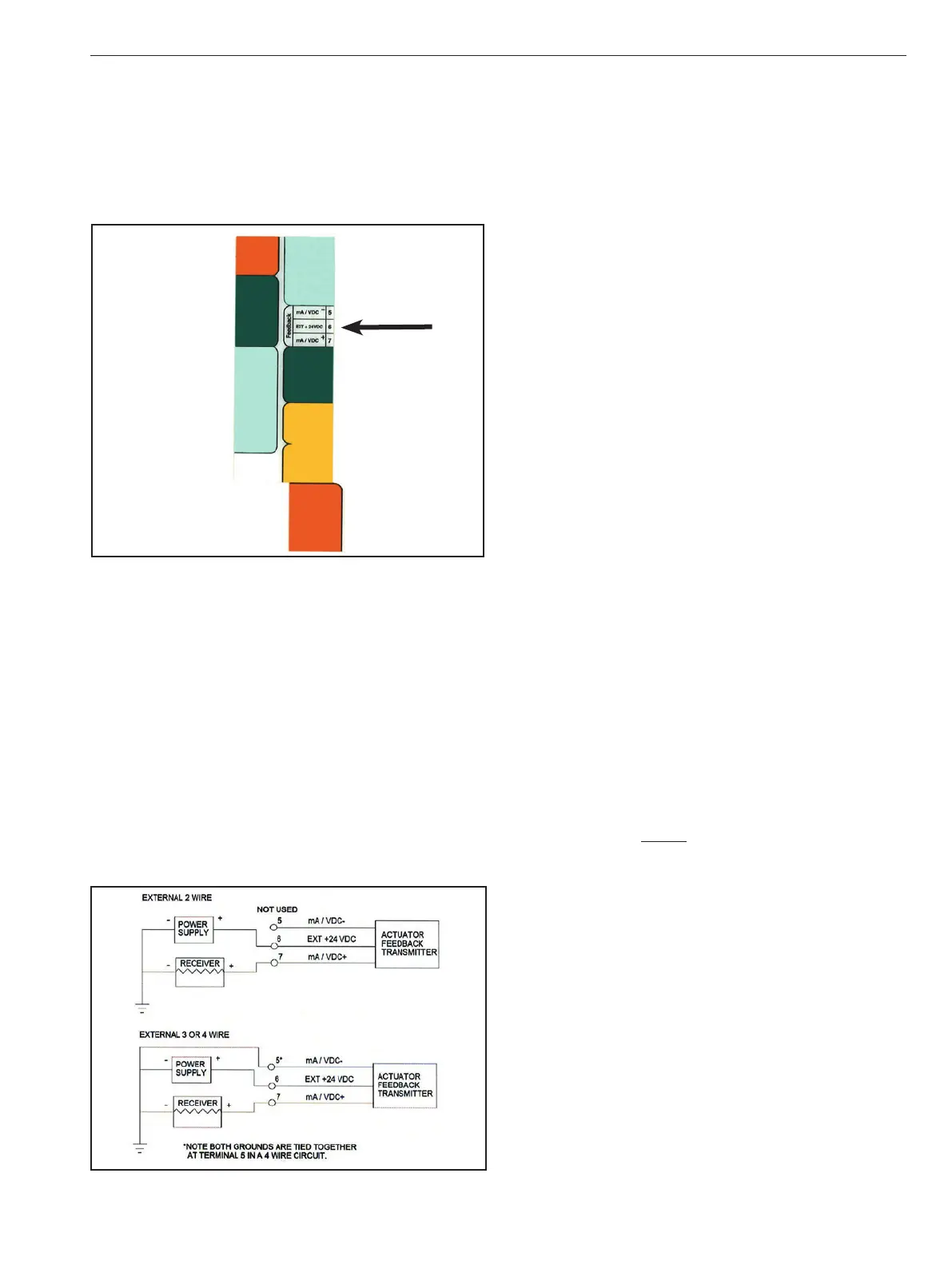
Describes how position feedback indicates actuator output position and its wiring for 4-20mA and 0-10VDC.

Status Indicators

Covers status indicators including auxiliary switches, power status relay, and battery status relay.

Power Management

Battery

Details the optional battery backup system, its charging, and maintenance requirements.

Power Fail Controls

Explains configuration options for actuator behavior upon loss of external power (Fail position).

"Wake Up"and Manually Drive Actuator

Describes how to wake the actuator from sleep mode and manually drive it using battery power.

Energy Save Mode

Explains the 'Energy Save' mode feature that reduces power consumption by 'dozing' the unit.

Board Installation / Replacement

Safety Precautions

Critical safety warnings for working inside the actuator cover with dangerous voltages present.

Safety Precautions Applicable to Units Equipped with a Back-Up Battery

Specific safety warnings for units with an optional battery, emphasizing potential actuator movement.

Parts Verification

Steps for verifying replacement board kits, inspecting parts for shipping damage, and collecting tools.

Board Removal

Step by Step Instructions for the Removal of a Universal ADC/LADC-Series Actuator Control Board

Detailed instructions for removing the actuator control board, including cover and overlay removal.

Board Installation

Step by Step Instructions for the Installation of a Universal ADC/LADC-Series Actuator Control Board

Provides step-by-step instructions for installing the replacement actuator control board, connecting cables and securing it.

Reassembly

Default Settings and Modes

Troubleshooting

General Operating Information

Enclosure Ratings and Product Certifications

Details enclosure specifications, NEMA ratings, and certifications like CSA and ATEX for ADC-Series actuators.

Operating Temperature Limits

Specifies the operating temperature range for ADC-Series actuators and recommendations for ambient temperature management.

Actuator Mounting

Provides guidelines for mounting the actuator in various positions, emphasizing secure attachment and alignment.

Manual Override

Instructions on how to use the manual override feature, including precautions to prevent actuator damage.

Lubrication

Information that the actuators' power train components are permanently lubricated and require no additional lubrication.

Problem Prevention

Highlights common issues arising from improper installation, wiring, setup, coupling, alignment, and mounting.

Warranty

Outlines the standard 2-year warranty for V-Series actuators and procedures for warranty claims.

Repair Service/Spare Parts

Provides contact information and procedures for obtaining repair services and ordering spare parts.

Specifications & Technical Information

ADC-Series Universal Control Board

Details control board specifications including input impedance, signal types, stall protection, and dead band.

Dimensions

Provides detailed dimensional drawings and specifications for ADC-Series actuator enclosures.

ADC-Series Actuators by Model Number

Additional Actuator Products and Accessories from Metso

Related product manuals