4. GENERAL INSTALLATION
INFORMATION
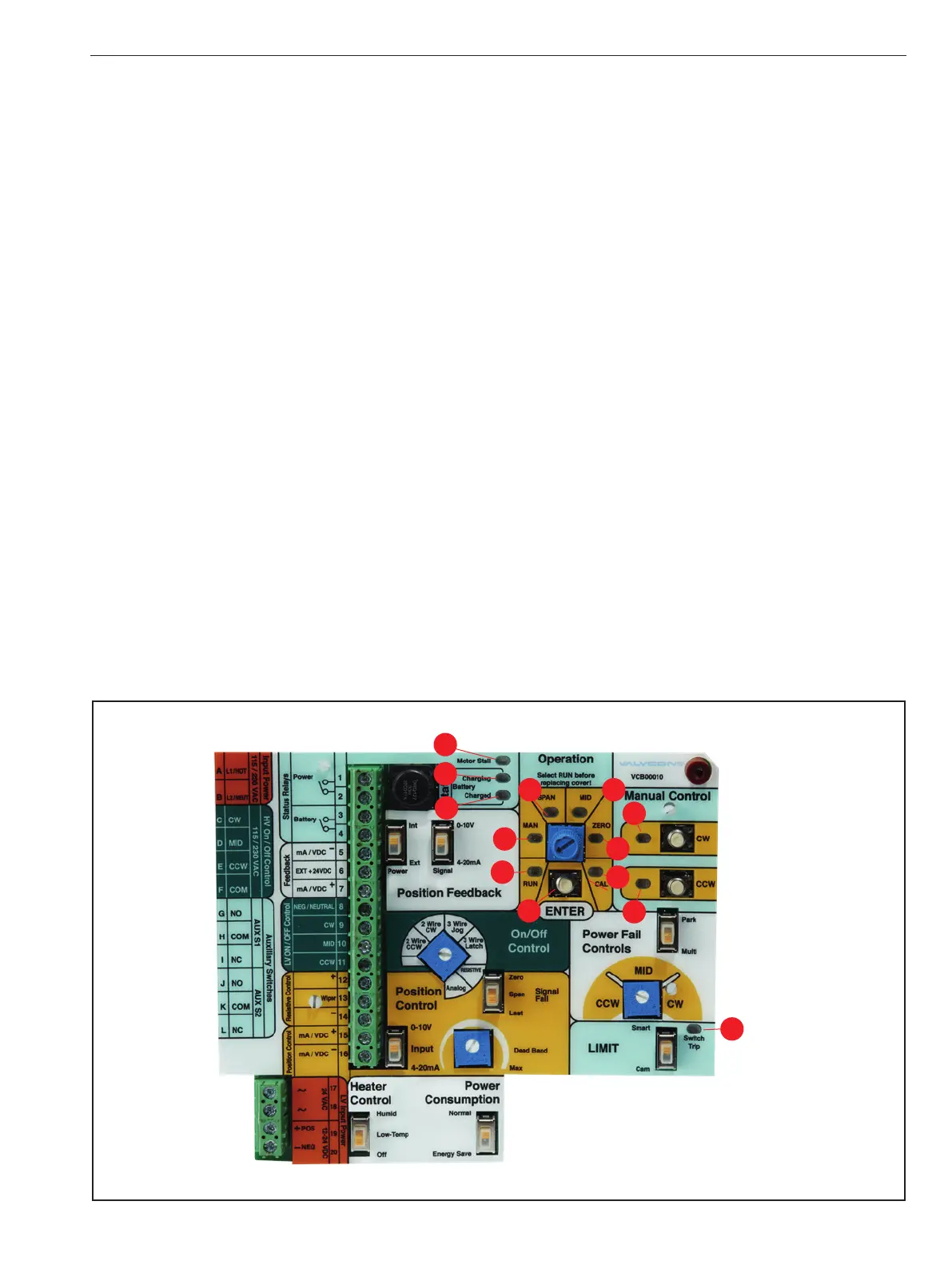
4.1 Interface
1 - CAL – A continuous yellow LED indicates that the CAL
(calibration) mode has been selected. A flashing yellow LED
displays to the user how close they are to hitting the CAL point
depending on the speed of the flashes. The CAL mode allows the
user to calibrate the position tracking potentiometer without
the use of an ohmmeter or other electronic instruments. In CAL
mode the actuator will travel beyond the saved settings for the
Zero and Span stop positions.
2 - ZERO – A continuous yellow LED indicates that the ZERO
mode has been selected. ZERO mode permits the user to
set the desired Zero end-of- travel stop position with a
corresponding control signal value. The Zero position is
typically the fully clockwise position and minimum control
signal value, but Zero may be set at any position.
3 - MID - A continuous yellow LED indicates that the MID
mode has been selected. MID mode permits the user to
save the desired “MID” position. The MID position may be
set at any position inside (between) the saved Zero and
Span end-of-travel positions. (MID is not typically used
with the Position Control configuration but can be used
as a mid-travel “fail” position upon loss of external power,
provided the actuator is equipped with a back-up battery.)
4 - SPAN – A continuous yellow LED indicates that the SPAN
mode has been selected. SPAN mode permits the user to set
the desired Span end-of-travel stop with a corresponding
control signal value. Typically, the Span position is the fully
counterclockwise position and maximum control signal
value, but Span may be set at any position.
5 - MAN (MANUAL) – A continuous yellow LED indicates that
Manual Control mode has been selected. The actuator will
not respond to external control signals and the [CW] and
[CCW] push buttons are enabled for manually driving the
actuator in either direction. In Manual mode the actuator
will not travel beyond the saved settings for the Zero and
Span stop positions.
6 - RUN – A continuous green LED indicates that the normal
operating mode has been selected. In RUN mode the actuator
will respond external signals supplied to the Universal Control
Board. This LED will turn off in Energy Save mode.
7 - ENTER – located directly below the mode selector and
permits the user to activate modes and confirm settings by
pressing the [ENTER] button.
8 - CW (CLOCKWISE) – A continuous yellow LED indicates
that the actuator is driving in the CW direction. Located
next to the Manual Control push button to drive the
actuator in the CW direction.
9 - CCW (COUNTER-CLOCKWISE) – A continuous yellow
LED indicates the actuator is driving in the CCW direction.
Located next to the Manual Control push button to drive
the actuator in the CCW direction.
10 - Motor Stall – A flashing red LED indicates a stall
condition exists and that the actuator has been prevented
from reaching the position commanded by the control
signal. A STALL of more than several seconds will cause
power to be automatically removed from the motor circuit,
placing the actuator in a safe mode. A reverse signal or a
manual mode [CW] or [CCW] movement is required to clear
the stall condition. A STALL condition can be initiated by
a blockage in the valve or damper, cam limit settings that
10
11
12
6
7
5
4 3
2
1
8
9
13
Figure 3
VCB00010 Universal Control Board (Front)
IMO 6/18
IMO-I4900 EN 5

 Loading...