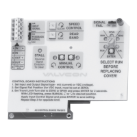
3.2 Universal Control Board P/N
VCB00010
The Universal Control Board can be configured for either
“Two-Wire” or “Three-Wire” On/Off control, or “4-20mA
Analog”, “0-10VDC Analog”, or a “Resistive” Positioner
Control. (See Figure 5 in Section 4.3)
The Universal Control Board used in Positioner Control
mode can be configured for Loss of Signal and has an
adjustable input signal Dead Band.
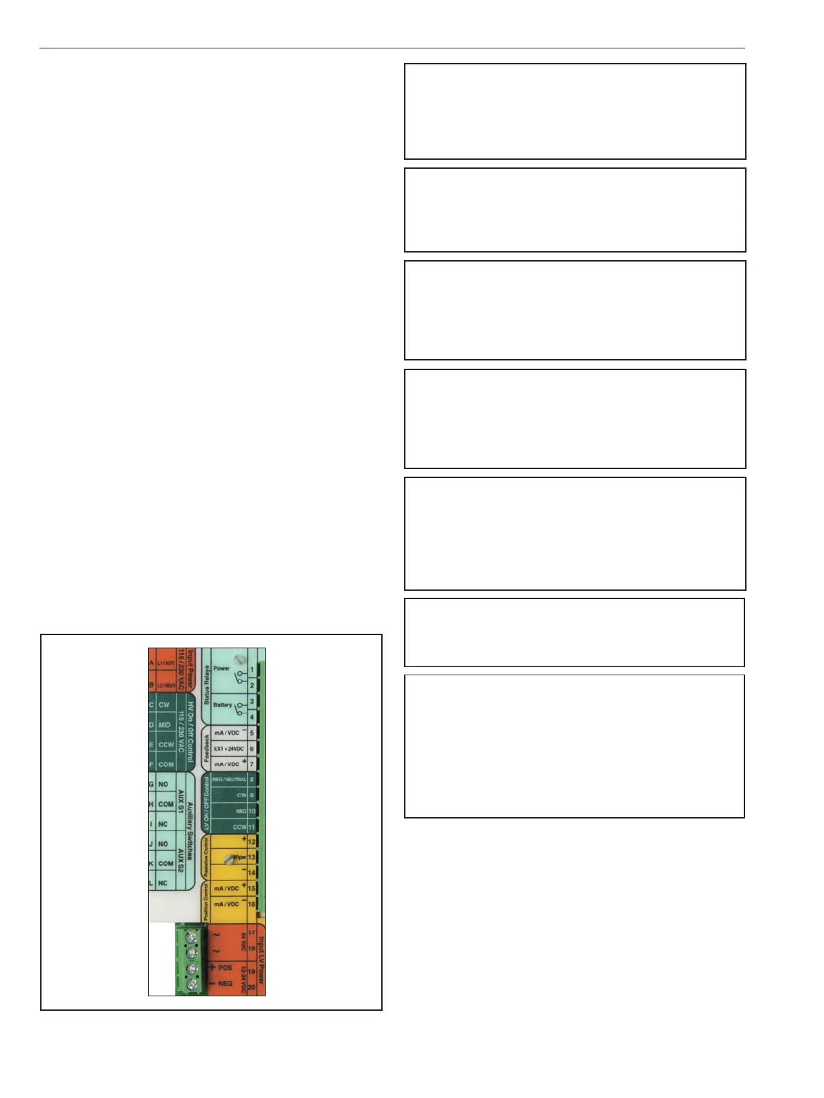
The Universal Control Board allows independent 115VAC,
230VAC, 12VDC, 24VDC or 24VAC control signals from
actuator power.
The Universal Control Board can provide analog position
feedback, Power and Battery status and includes on-board
battery status indicators.
The Universal Control Board with the optional Battery Back-
up installed will allow you to select power “Fail” position
as well as to choose “Park” or “Multi” cycling upon loss of
actuator power.
The Universal Control Board has locked rotor stall protection.
The Universal Control Board has manual push button control
and simple digital smart set functionality for entering and
saving precise end of travel positions for calibration to the
application.
The Universal Control Board has an easy to navigate color
scheme for its input and output wiring terminal blocks,
detailed below:
Orange = Actuator Power
Green = On/Off Control
Yellow = Modulating Control
White = Analog Feedback
Light Blue = Status Feedback
WARNING
DANGEROUS VOLTAGES ARE PRESENT INSIDE THE ACTUATOR
COVER UNLESS THE POWER SUPPLY TO THE ACTUATOR HAS BEEN
SHUT OFF OR DISCONNECTED. USE EXTREME CAUTION WHENEVER
WORKING ON THE ACTUATOR WITH THE COVER REMOVED.
WARNING
ACTUATORS SHOULD BE PROPERLY GROUNDED AND WIRED IN
ACCORDANCE WITH LOCAL ELECTRICAL CODE; SEE NAMEPLATE
FOR MAXIMUM CURRENT DRAW.
WARNING
DO NOT MIS-APPLY HIGH-VOLTAGE SIGNALS TO LOW-VOLTAGE
CIRCUITS. DO NOT POWER THE POSITION FEEDBACK CIRCUIT IF
EXTERNAL POWER MODE IS NOT SELECTED.
SERIOUS DAMAGE TO THE CIRCUIT BOARD MAY RESULT.
WARNING
WHENEVER WORKING INSIDE THE ACTUATOR, CARE MUST BE TAKEN
TO AVOID DAMAGE TO THE MACHINED FLANGE SURFACES ON THE
COVER AND BASE CASTINGS. FAILURE TO DO SO CAN VOID THE
ACTUATOR’S ENVIRONMENTAL CERTIFICATION.
WARNING
USE CARE WHENEVER WORKING WITH THE ACTUATOR COVER
REMOVED. DAMAGE, SCRATCHES, OR DENTS ON THE MACHINED
FLANGE SURFACES OF THE ENCLOSURE MAY VOID COMPLIANCE
WITH NEMA, CSA, UL, AND/OR IEC SPECIFICATIONS. (SEE SECTIONS
6.3.5, 7.3.5, & 13)
WARNING
IF USING 24VAC TO POWER THE ACTUATOR, A DEDICATED POWER
SUPPLY OR ISOLATION TRANSFORMER MUST BE USED.
WARNING
WHEN OPTIONAL BATTERY IS CONNECTED TO BOARD, THE
UNIT MAY DRIVE!
BEWARE OF MOVEMENT OF THE FINAL DRIVE ELEMENT AND ANY
LINKAGE BETWEEN IT AND THE ACTUATOR!
KEEP HANDS, OTHER PARTS OF THE BODY, TOOLS AND OTHER
OBJECTS OUT OF THE WAY OF MOVING PARTS. FAILURE TO DO THIS
MAY RESULT IN DAMAGE OR PERSONAL INJURY!
Figure 2
IMO 6/18
4 IMO-I4900 EN

 Loading...