CHAPTER 11: MUB-MINA/LINA U-BRACKET
64
MUB-MINA/LINA CEILING-MOUNT CONFIGURATIONS
The MUB-MINA/LINA U-bracket can be mounted to a ceiling to aim a single LINA loudspeaker, or it can be used for arrays
of up to five LINA loudspeakers when using the four 1/4-inch corner holes (see Table 11). The MUB-MINA/LINA U-bracket
should be secured to the ceiling with fasteners placed in its four 1/4-inch, corner holes. Make sure to use fasteners appro-
priate for the ceiling surface and rated to meet or exceed the weight of the MUB-MINA/LINA and loudspeakers. The LINA
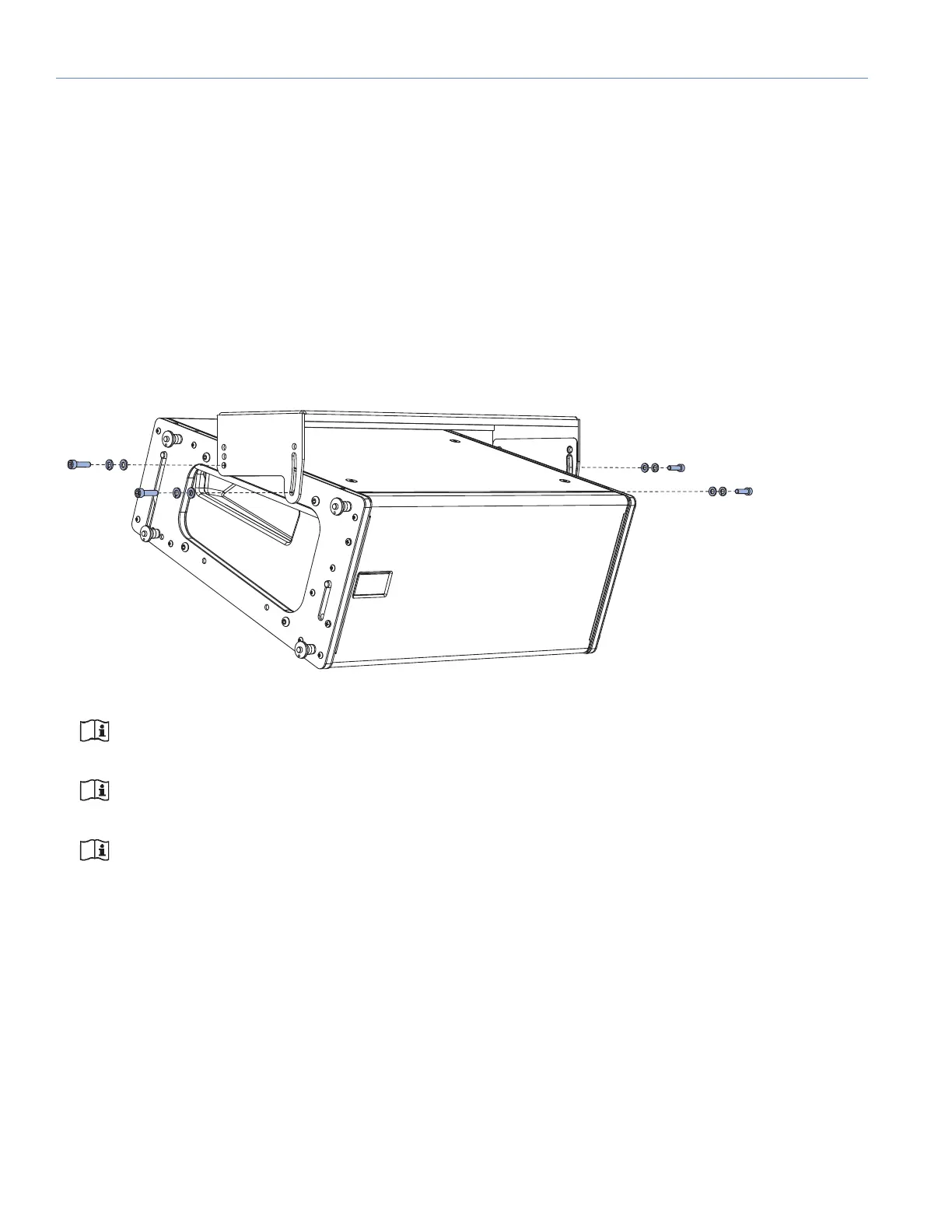
cabinet is secured to the U-bracket with the screws and washers included with the MUB-MINA/LINA kit. Additional cabinets
are attached to the top cabinet with the top unit’s GuideALinks.
For ceiling-mounted configurations, the MUB-MINA/LINA can be oriented for either maximum downtilt (with the slot near
the front of the loudspeakers) or maximum uptilt (with the slot near the rear of the loudspeakers).
• For a single flown cabinet, the MUB-MINA/LINA supports continuous angles of 0 to –20 degrees in the maximum down-
tilt orientation, and angles of +10 to –10 degrees in the maximum uptilt orientation.
• For multiple flown cabinets, the MUB-MINA/LINA supports fixed angles of 0, –5, and –10 degrees depending on the ori-
entation.
NOTE: For multiple cabinets, the MUB-MINA/LINA slot is not recommended for variable adjustments since the
angle could change over time due to the weight of the cabinets.
NOTE: For illustrations showing which MUB-MINA/LINA mounting holes and slot configurations to use to
achieve specific angles for ceiling-mount applications, see Table 12 and Table 13 on page 60.
NOTE: The center of gravity of the array will indicate specific truss attachment points that do not cause rota-
tional tension. The attachment points should be tightened while in this “balanced” position and the final tilt of
the loudspeaker(s) evaluated for desired coverage.
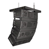
Figure 56: Ceiling-Mounted MUB-MINA/LINA with One LINA
 Loading...