Part 5
-
Electrical Components and Wiring Diagrams
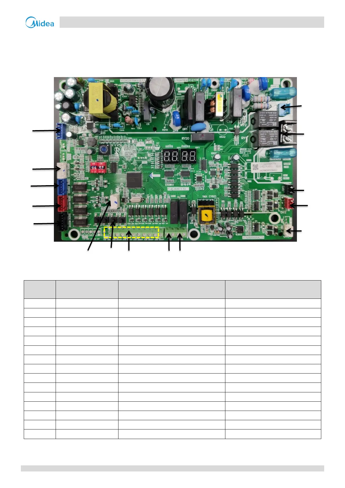
6 Mode Selection Box Main PCB
6.1 Ports
MS01
Figure 5-6.1: MS01 main PCB ports
1
Notes:
1. Label descriptions are given in Table 5-6.1
Table 5-6.1: MS01 main PCB ports
Temperature sensor(T1C1,T2C2) connection
Electric ball valve A connection
Electric ball valve B connection
Electric ball valve C connection
Electric expansion valve A connection
Refrigerant sensors connection
Ventilation fan connection
Communication port to outdoor unit
Communication port to indoor unit
Communication port to monitor

 Loading...