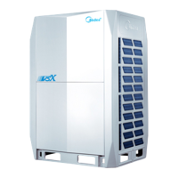
V6R VRF 50/60Hz
81
Part 5 - Electrical Components and Wiring Diagrams
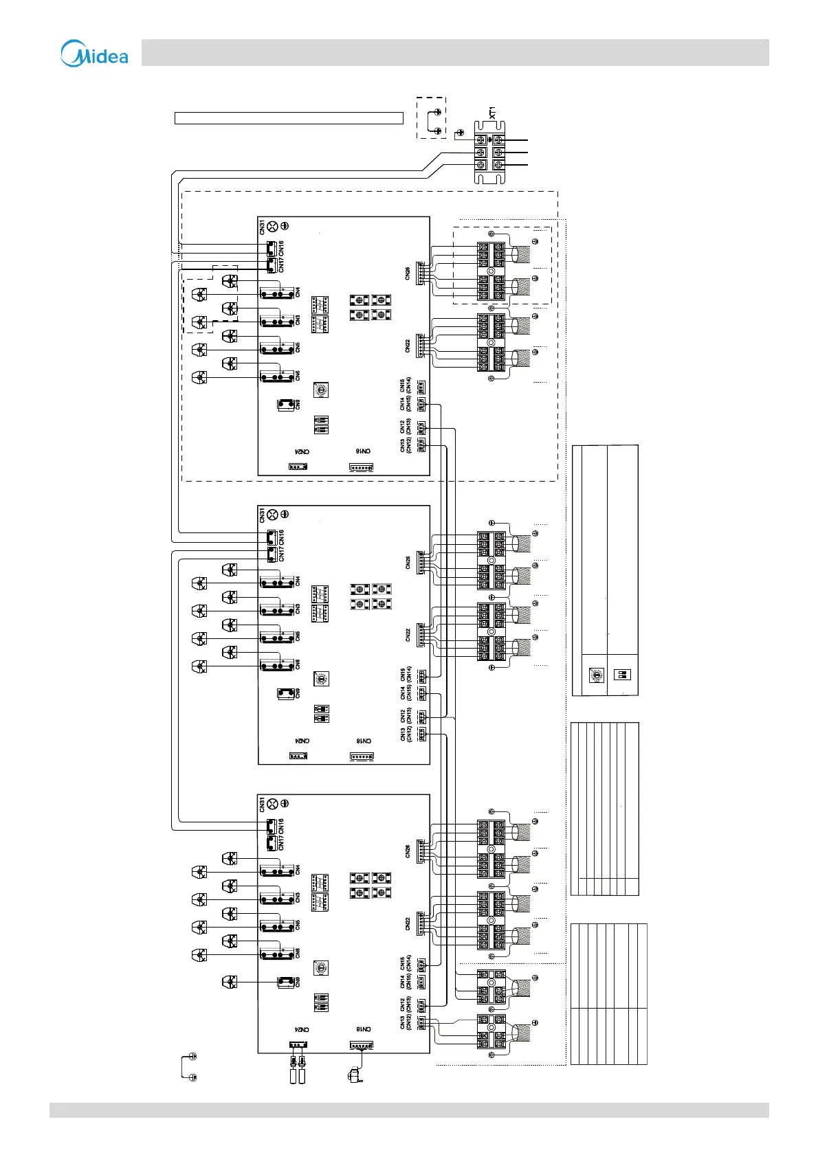
Figure5‐7.4:MS08/MS10/MS12wiringdiagram
Indoor No. 9
M-O M-O
1(M-I) 2(M-I) 3(M-I) 4(M-I)
SW1 SW2
Brown
Red
White
Blue
Brown
Red
White
Blue
Indoor No. 10 Indoor No.11 Indoor No. 12
SW3 SW4
M-M M-M
P Q E P Q E P Q E P Q E
Indoor No. 5
M-O M-O
1(M-I) 2(M-I) 3(M-I) 4(M-I)
SW1 SW2
Brown
Red
White
Blue
Brown
Red
White
Blue
Indoor No. 6 Indoor No. 7 Indoor No. 8
SW3 SW4
M-M M-M
P Q E P Q E P Q E P Q E
SVP
T1C1
To outdoor or MS units
communication bus
To indoor units communication bus
Outdoor
/Upstream MS
Downstream MS
T2C2
Blue
Red
Yel low
Gray
XS2 XS1
XP2 XP1
Gray
Yel low
Blue
The wiring picture shown is for reference only, actual product may vary.
CODE NAME
XT1 Terminal block
XS1~XS2 Connectors
XP1~XP2
Connectors
T1C1~T2C2 Temperature sensor
SV#A-X, SV#B-X
SVP
EEVA Electronic expansion valve
Solenoid valve
P Q E
G/Y
P Q E
SV1B-1 SV2B-2 SV3B-3 SV4B-4
SV1A-1 SV2A-2 SV3A-3 SV4A-4
SVP
Yellow
Black
Yellow
Black
Yellow
Black
Yellow
Black
SV4
SV3
SV2
SV1
SV1B-5 SV2B-6 SV3B-7 SV4B-8
SV1A-5 SV2A-6 SV3A-7 SV4A-8
SVP
Yellow
Black
Yellow
Black
Yellow
Black
Yellow
Black
SV4
SV3
SV2
SV1
SV1B-9 SV2B-10 SV3B-11 SV4B-12
SV1A-9 SV2A-10 SV3A-11 SV4A-12
SVP
Yellow
Black
Yellow
Black
Yellow
Black
Yellow
Black
SV4
SV3
SV2
SV1
EEVA
Blue
Red
Blue
Red
Indoor No. 1
M-O M-O
1(M-I) 2(M-I) 3(M-I) 4(M-I)
SW1 SW2
Brown
Red
White
Blue
Brown
Red
White
Blue
Indoor No. 2 Indoor No. 3 Indoor No. 4
SW3 SW4
M-M M-M
P Q E P Q E P Q E P Q E
POWER
DSP1
DSP2
S1 S2
ONON
ENC2(0)
POWER
DSP1
DSP2
S1 S2
ONON
ENC2(1)
POWER
DSP1
DSP2
S1 S2
ONON
ENC2(2)
EEV_A
EEV_A
EEV_A
Guide for main control panel dial code
ENC2
● S1:11 means synchronous control for 2 ports
(First PCB is port 1 and 2, Second PCB is port 5 and 6, third PCB is port 9 and 10)
● S2:11 means synchronous control for 2 ports
(First PCB is port 3 and 4, Second PCB is port 7 and 8, third PCB is port11 and 12)
MS PCB number
(Factory setting, can’t be changed. 0 means the first PCB, 1 means the second
PCB, 2 means the third PCB)
LN
Power in
Blue
Red
G/Y
S1/S2
ON
(00 is default)
12
ON
T1C1
T2C2
T1C1
T2C2
T1C1
T2C2
G/Y
DSP1 and DSP2 display content
E3
Communication between master and slave control boards
failed
Malfunction of subcooler outlet thermistor(T1C1)
E4 Malfunction of subcooler inlet thermistor(T1C2)
H0
Communication failure between MS and master outdoor unitE2
LL
S1+S2 dialing setting error
FE
MS has no address when first powered on
EEPROM errorE7
Black
Black
Black
Green
Black
Green
Black
Green
Black
Green
Black
Green
Black
Green

 Loading...