Chapter 4. Troubleshooting
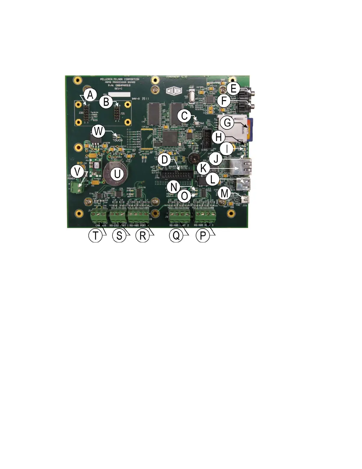
4.3.1. Processor board (P/N: 08BHPAR91_)
Figure 33: 08BHPAR91_, Revision C
A. Connector J20: USB connections for wifi (not used)
B. Connector J21: SPI connections for wifi (not used)
C. Switch SW1: system reset
D. Connector J2: JTAG port for factory programming
E. Connector J17: audio out (not used)
F. Connector J18: audio/mic in (not used)
. Socket J1: SD card and socket
H.
I.
J.
K. Connector J5: RJ45 for ethernet
L. Connector J11: USB host
M. Connector J10: mini USB (not used)
N. Light D22: receive
O. Light D23: transmit
P. Connector J9: RS485 port 3 (communication with input/output board)
Q. Connector J8: RS485 port 2 (not used)
R. Connector J6: RS485 port 1 (not used)
S. Connector J7: RS232 port 1 (not used)
T. Connector J1: serial port for CAN bus (not used)
G
Light D5: processor heartbeat
Light D3: 5 volts
Light D4: 3 volts
PELLERIN MILNOR CORPORATION
47
 Loading...