© 2009 MIMAKI ENGINEERING CO.,LTD.
6.4.7 P.1
1
2
3
4
5
6
7
8
R.1.1
Maintenance Manual > Disassembly and Reassembly > Drive System > GR Roller Assy
Model CJV30/TPC Issued 2008.08.04 Revised 2008.09.17 F/W ver. 1.20 Remark
1.1
6.4.7 GR Roller Assy
Work procedures
1. Remove the following covers.
• CY Cover F
• Cartridge Cover
• Maintenance Cover L
• Left Cover
• Left Station Cover
• Heater connector Cover
• MS Cover 2
• MS Cover 1
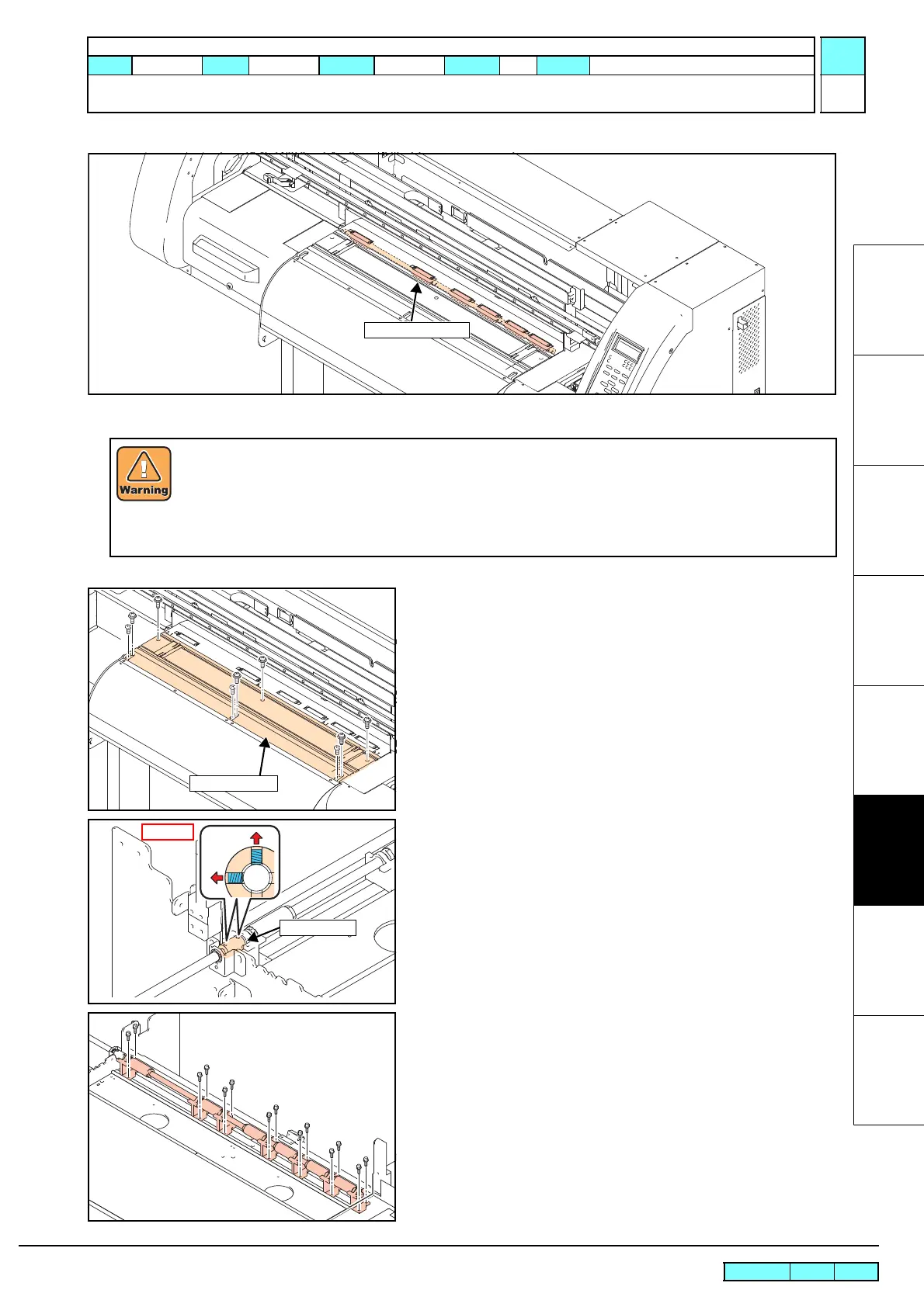
2. Remove the connector of pre-heater and print heater and then
remove the platen cover R and platen C30.
3. Loosen all PF coupling set screws.
4. Remove all GR roller 30 set screws from the lower part of the
spike shaft.
After turning off the sub and main power switches, unplug the power cord. Make sure to take15 minutes
before restarting the operation.
It is very dangerous if sleep mode functions mistakenly during the operation.
Moreover, the PCB may be damaged in case electric charge still remains inside.
Also, there is a possibility of electric shock because of high power voltage applied to the high-pressure
part of the power supply PCB assy. Take care to avoid contact with it.
 Loading...


