5-24 Image Optimization
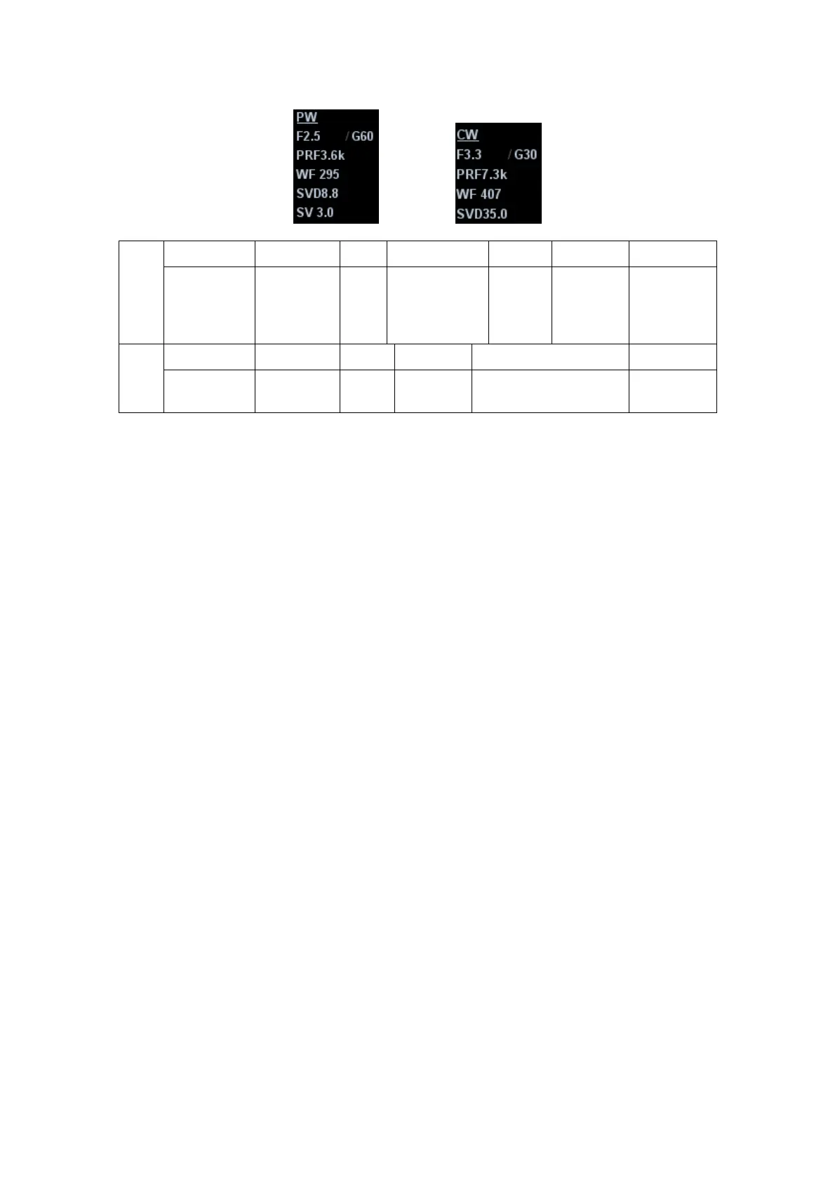
PW Display F 2.5 G 60
PRF 3.6k WF295
SVD 8.8 SV 3.0
Parameters
Frequency
Gain
Pulse
Repetition
Frequency
PRF
WF
(Wall
Filter)
SV
Position
SV Size
CW
Display F 3.3 G 30 WF407 PRF 7.3k SVD 35.0
Parameters
Frequency
Gain WF (Wall
Filter)
Pulse Repetition
Frequency PRF
SV
Position
During PW/ CW mode imaging, menus for B mode and PW/ CW mode are displayed
in the soft menu at the same time, use the left/right keys of soft menu controls <4> to
switch the among menus of B mode and PW/ CW mode.
In PW/CW mode, acoustic power of the probe is synchronous with that of B mode.
When you adjust the depth of the B mode image, related changes will occur in
PW/CW Mode image as well.
Most of the parameters are the same for the PW mode and CW mode, so parameters
of the both are combined together to be introduced here.
Items that appear in the menu or the soft menus are dependent upon preset, which
can be changed or set through "[Setup] -> [Image Preset]"; please refer to "5.16
Image Preset" for details.
Press <Update> to switch between the real-time B and freezing B images.
Only phased probes support CW mode.
5.7.3 PW/CW Doppler Mode Optimization
Gain
Description
This function is intended to adjust the gain of spectrum map. The real-time
gain value is displayed in the image parameter area in the upper left corner
of the screen.
Operation Rotate the <iTouch> knob clockwise to increase the gain, and
anticlockwise to decrease.
Or adjust it in the image parameter area.
Effects Increasing the gain will brighten the image and you can see more received
signals. However, noise may also be increased.
Frequency
Description
Refers to the operating frequency in PW mode of the probe, the real-time
value of which is displayed in the image parameter area in the upper left
corner of the screen.

 Loading...